1.5 The Tower
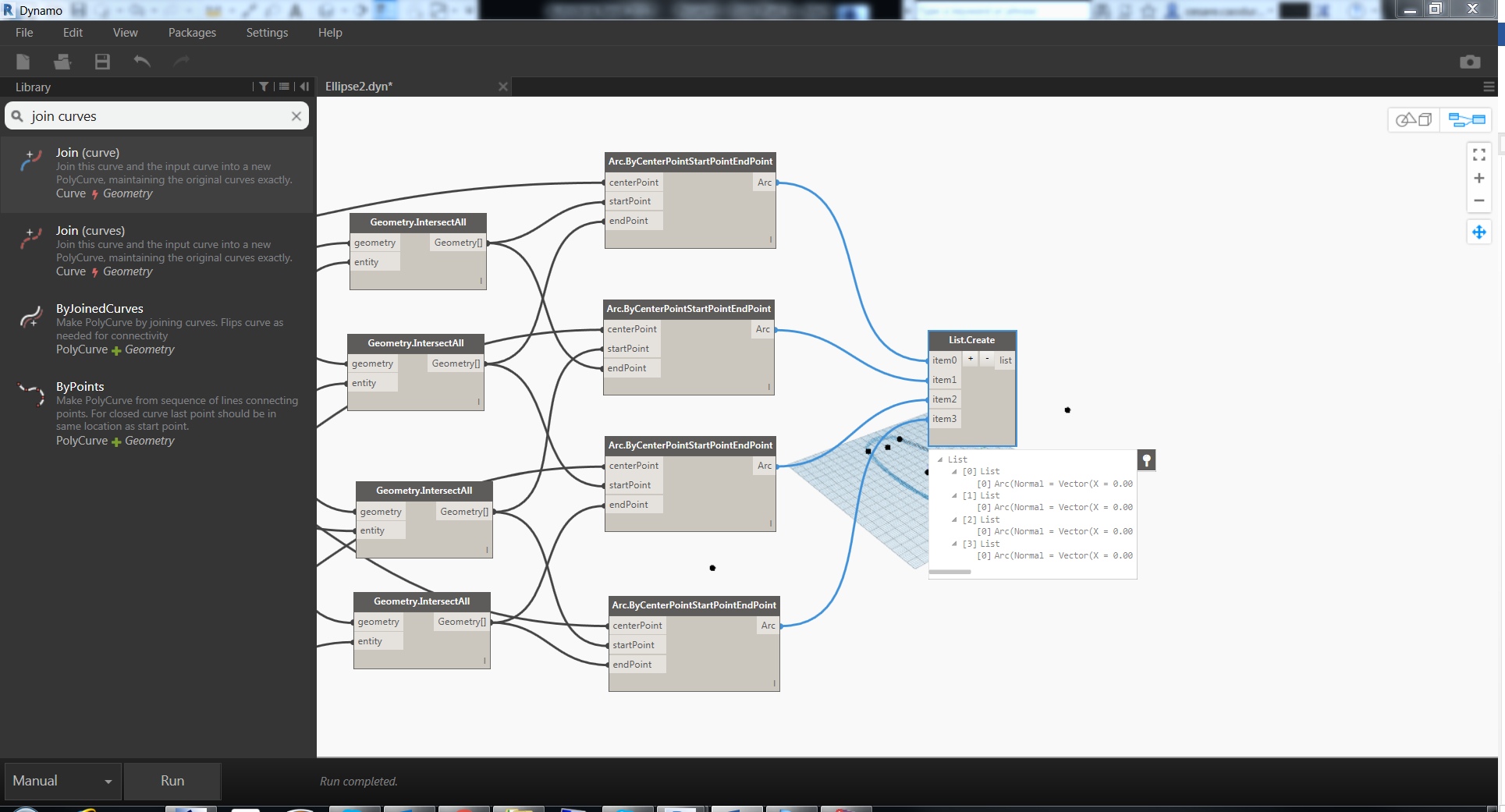
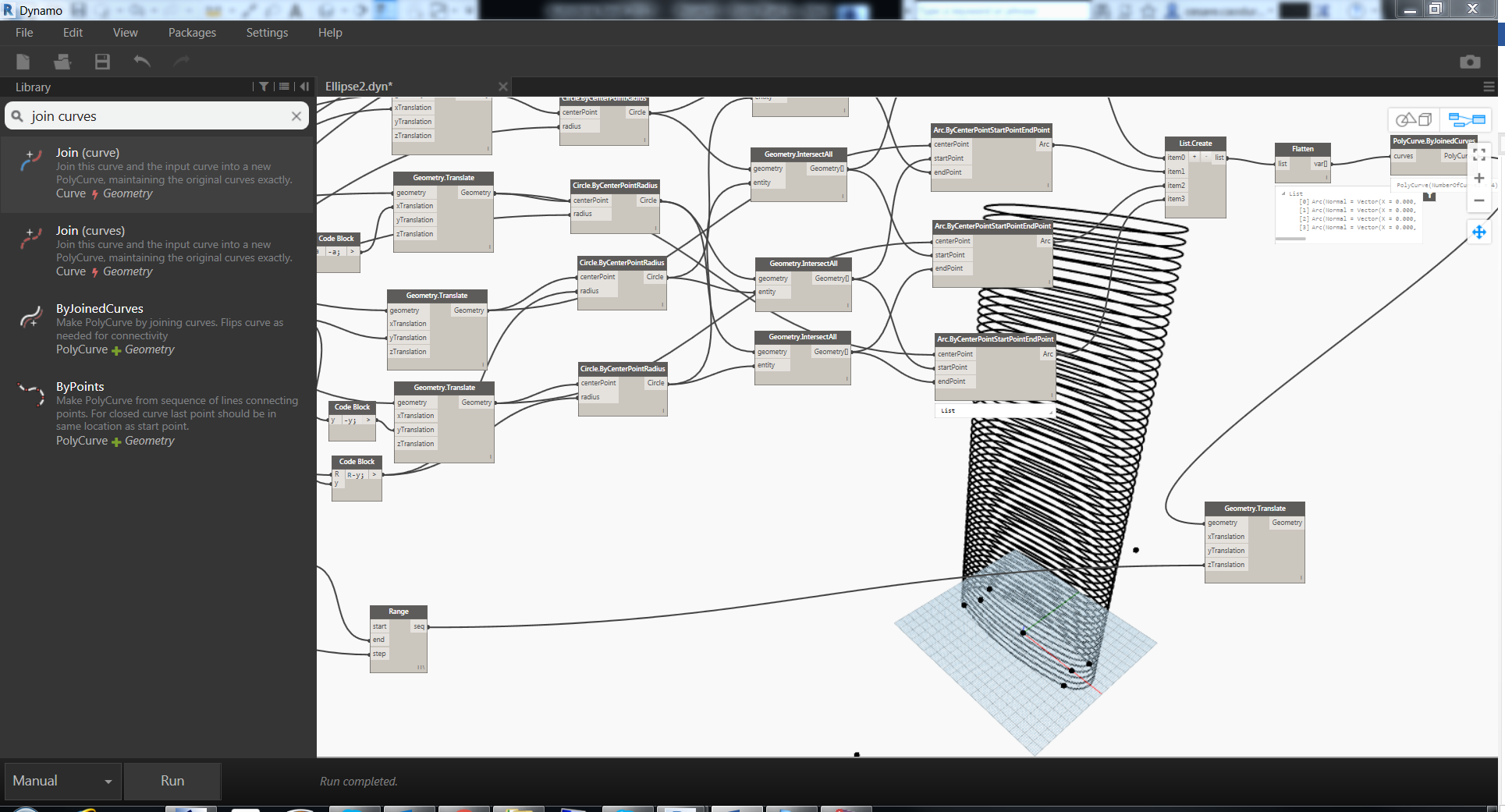
The final section is still made by 4 different curves and we need to join them into one single curve. Is a very common step and to do this, first of all, we need to create a list of curves. The node List.Create is one of the most used node in Dynamo and it will be useful in thousands of circumstance. Depending on the number of input that you want to put together, you can add or remove items from the list by clicking on the plus or minus icon.
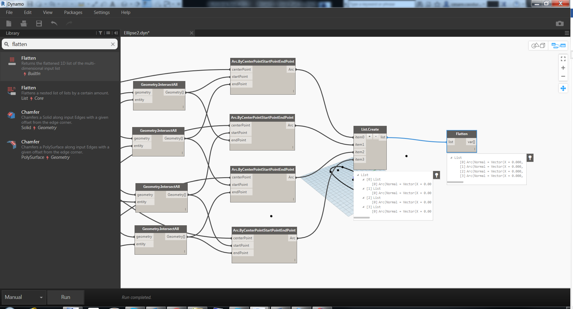
 In this case the result of the list node is a nested list but, to join the curves we need a flatten list (have a look on the dynamo website to better understand the logic of the list) and there’s a specific node to flatten all the lists.
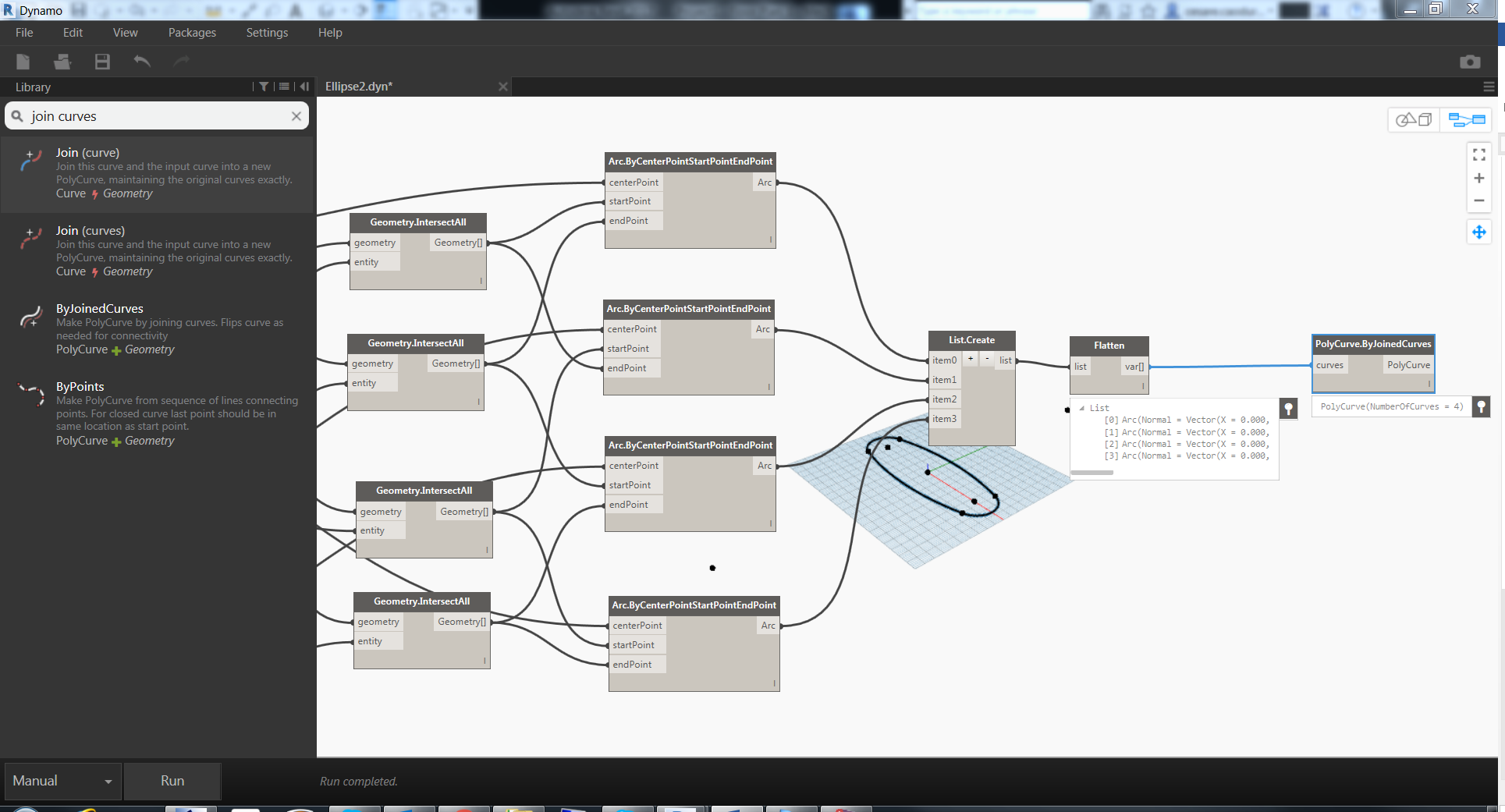
 Finally we can use the PolyCurve.ByJoinedCurves to merge all the curves into one curve.
 Now we have a type section for the floor and we can build our tower. First of all I changed my units in Revit to be in meters so we can deal with small numbers in our inputs.
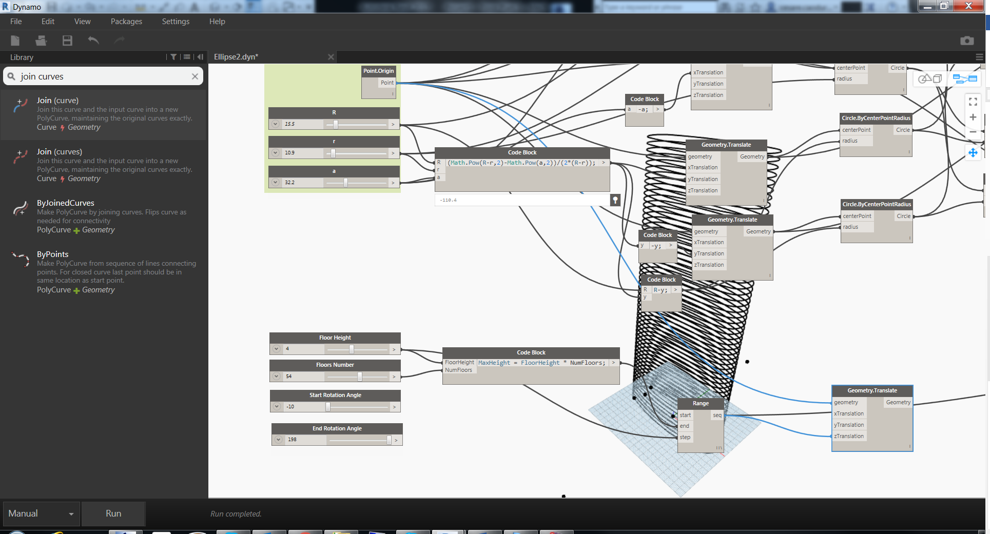
Again before starting we need to think about what we need as input to achieve our result:
- Number of floors (Integer Slider)
- Distance between floors
- Floor rotation
- Start rotation angle
- End rotation angle
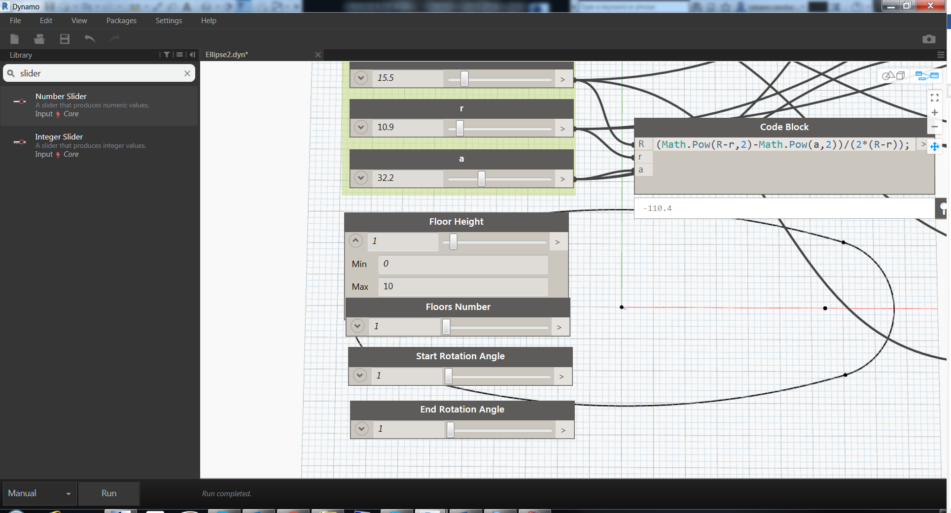
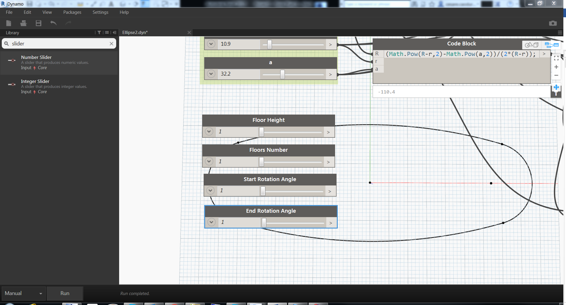 It’s possible to manage the range of each slider in the node properties. Open the small arrow on the left of the slider to access the min\/max range
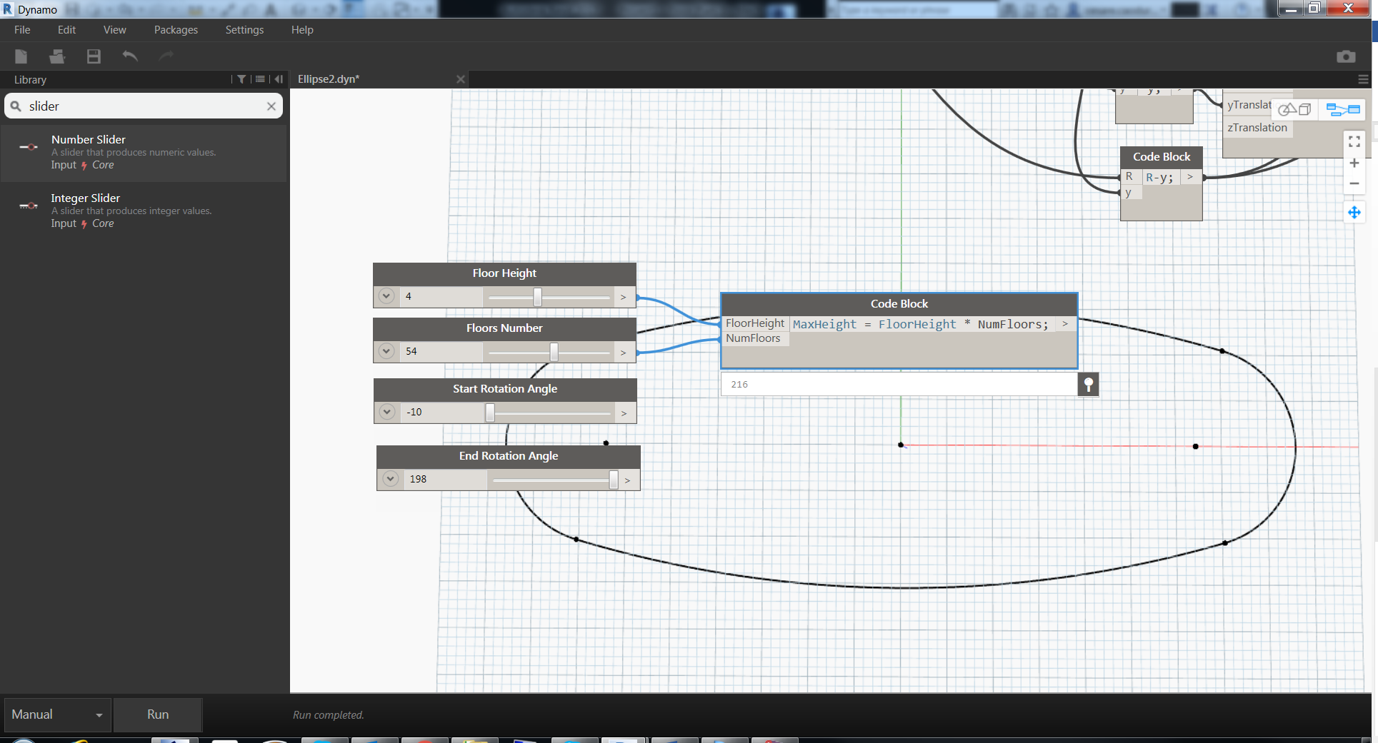
 The maximum height of the tower will be MaxHeight = FloorHeight * NumFloors. We can easily use a code block to calculate this value.
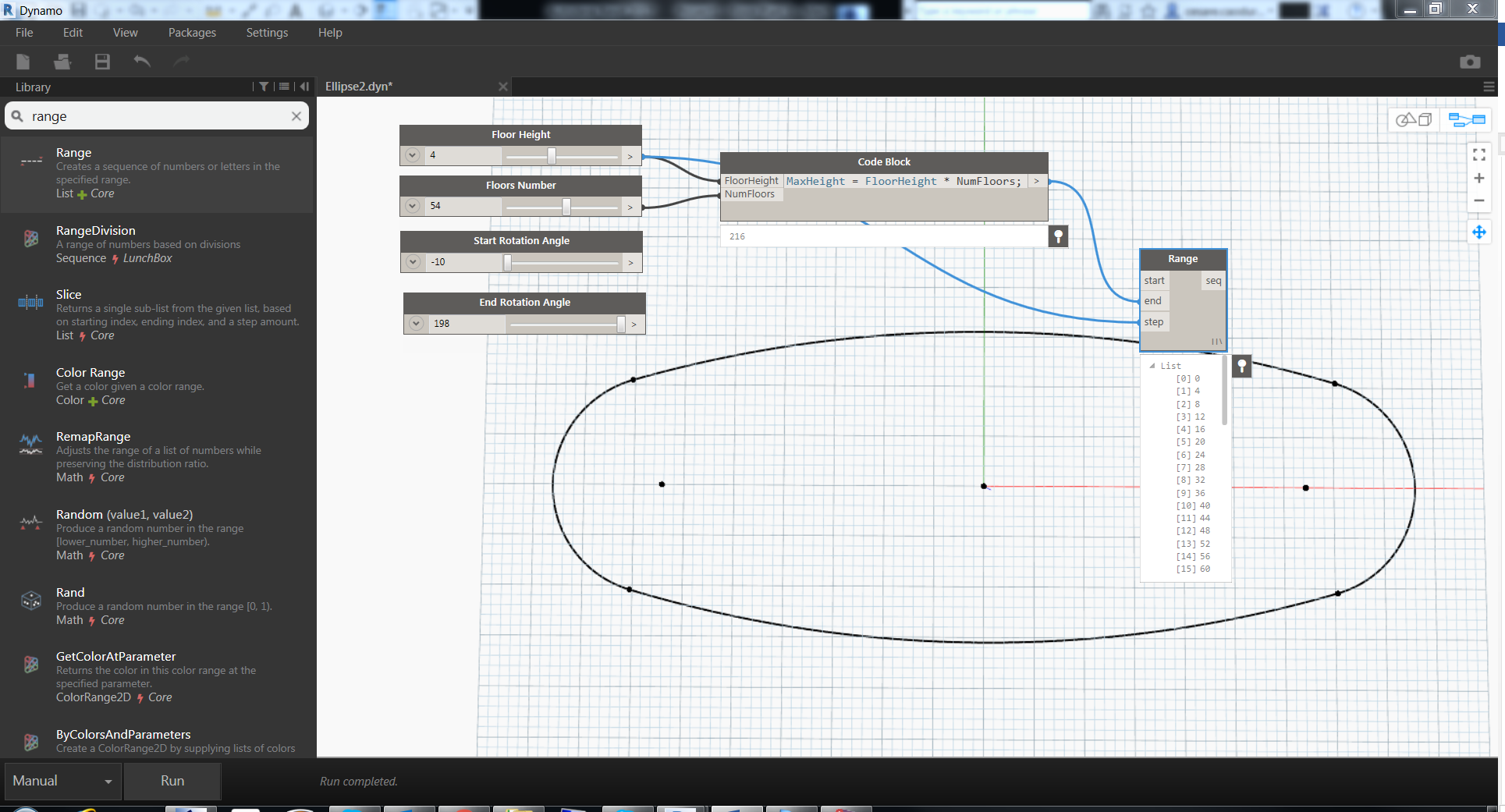
 With this we only have the total amount but we need the elevation of each floor as a list of levels. As always many ways but I want to show you a new node that will help to create a range of values with a starting value, ending value and step. The default value is 0 then the end value is the maximum height and the step is the floor height.
 Do you remember how to translate a geometry and at the same time copy this geometry? Exactly! Geometry.Translate and the amazing thing is, if you fill the input of the geometry with a list you’ll get all the copies just in one node.
So what are you waiting for? Just fill the curve into the geometry and the zTranslation and click run.
 Good…the tower is here! We are almost at the end of this tutorial and your tower now need a little bit of twisting before the external surface.
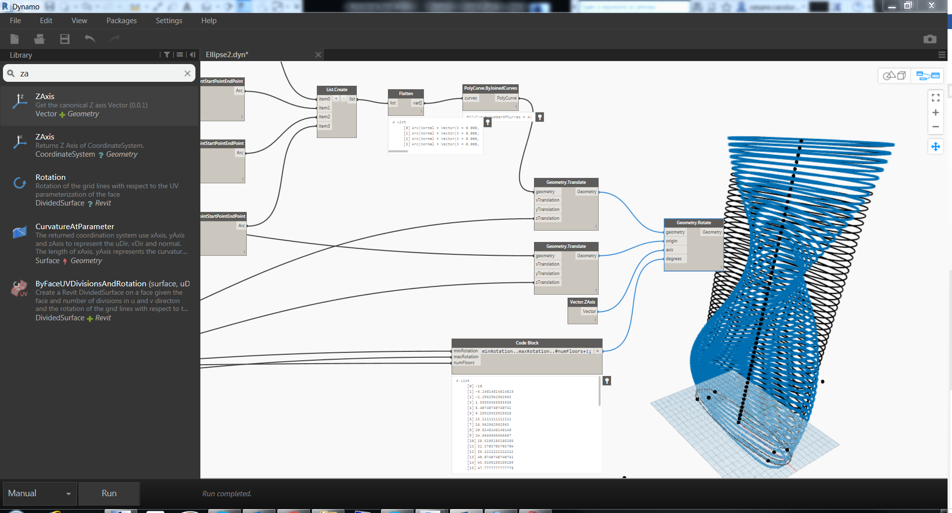
The logical behind the rotation is similar to the translation but we need some more information. The node is Geometry.Rotate and as input we need: geometry (of course), origin of the rotation, axis of rotation and degrees of rotation.
The origin will be the translation of the origin at the elevation of each floor (you know how to do it), the axis, according to the world coordinate system is the Z axis, and for the degrees of rotation we’ll create a range using our input values.
First we can create the translation of the origin point.
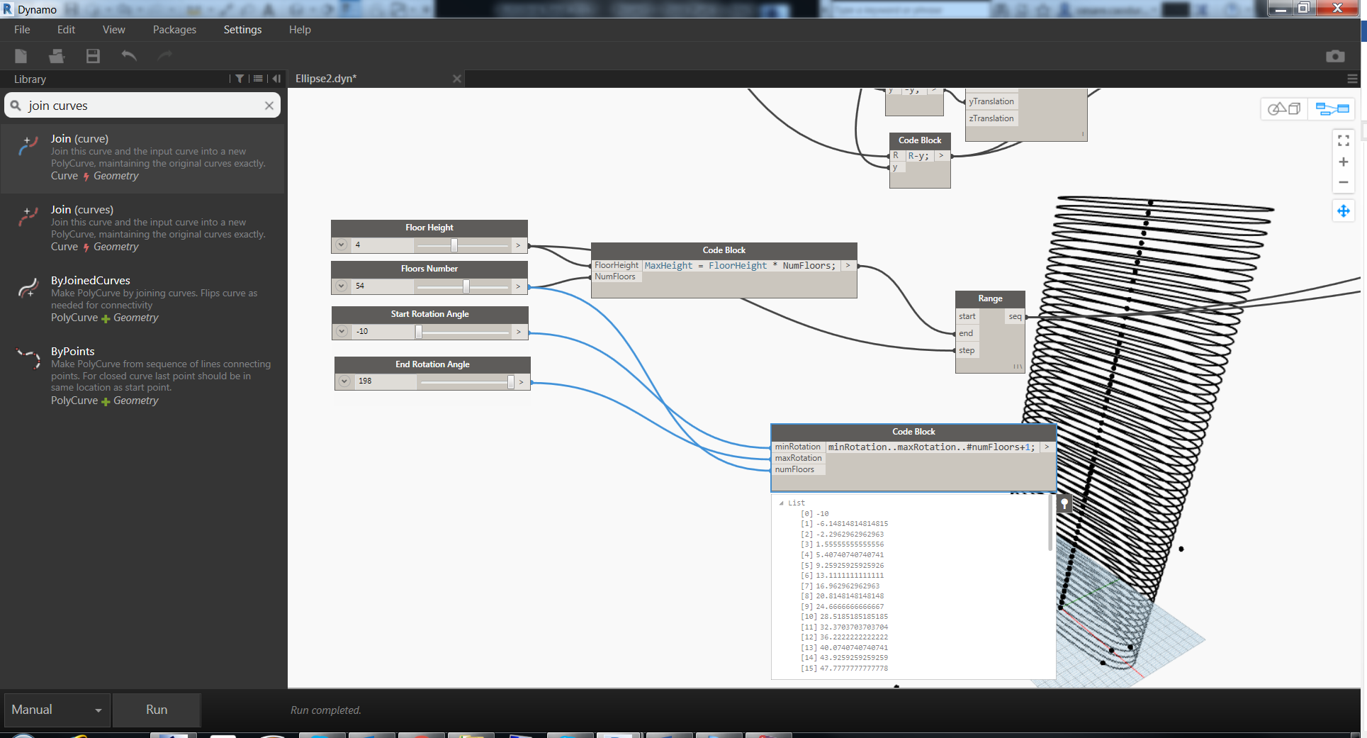
 For the rotation range this time we’ll use a code block with a particular syntax
minValue..maxValue..#numberValue+1
minRotation..maxRotation..#numFloors+1
Why plus 1? Because all the list has a first index the number 0 so is important in arrays to consider one step more. For example 54 floors means 0 to 53 that’s why we need to consider one more.
 Now we are ready to rotate the geometries, the only thing we will search in the node library is the ZAxis node.
 Hide
Hide
We can hide the Geometry.Translate node with the aligned section just to see the rotate sections
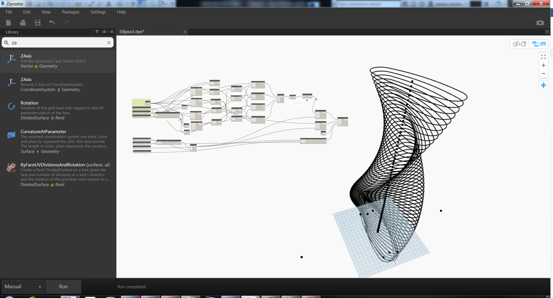 We came to the end, the latest node is the Surface.ByLoftwhich is accepting a list of curves as cross sections curves and basically is able to interpolate all these curves with a surface.
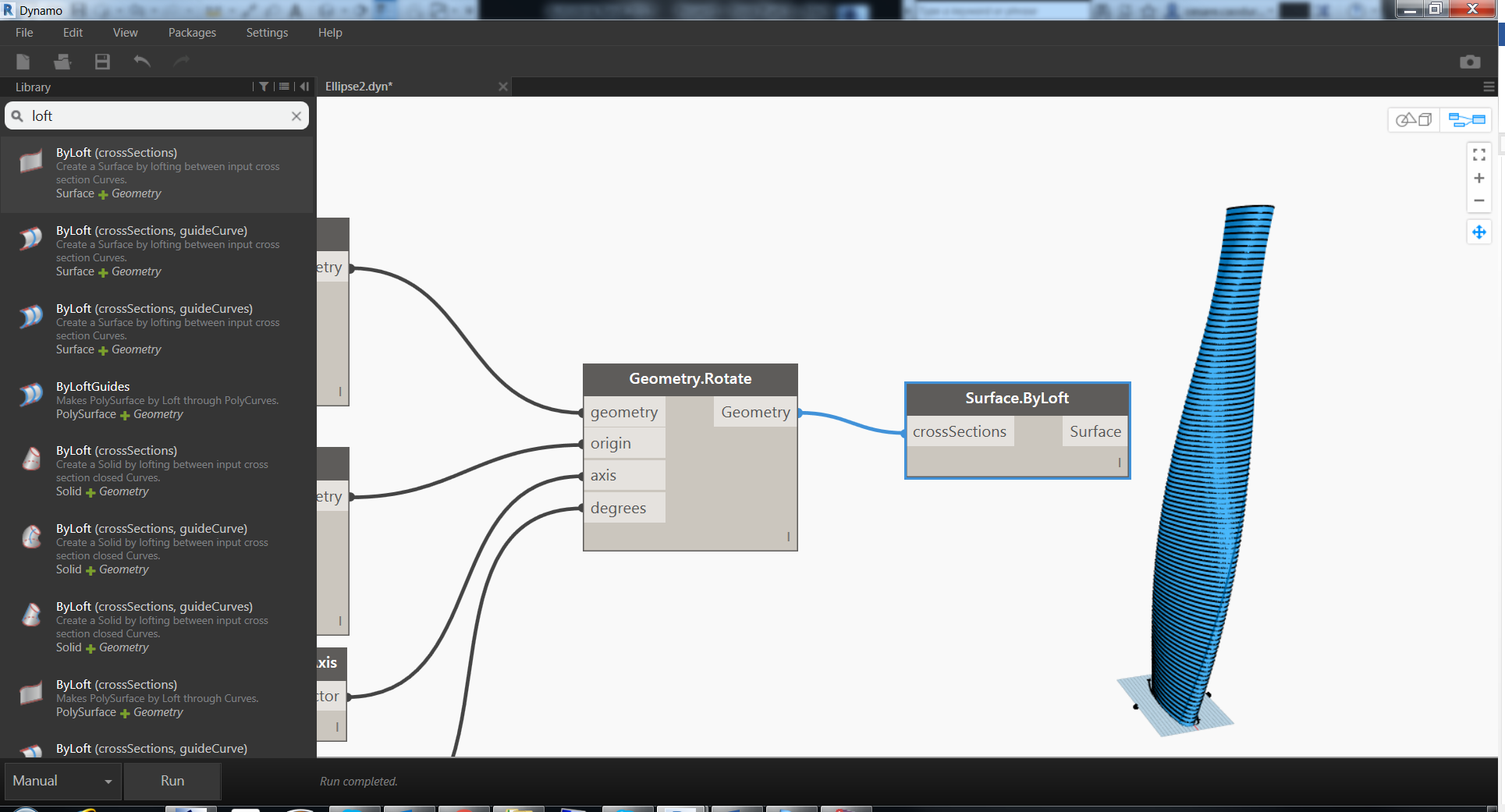 I’m very pleased to present you your brand new twisting tower.
I hope that this tutorial is useful not only as a step by step but as a starting guide on how to think when you approach to computational design. Now is time to use this tower in Revit…but this is another story for another tutorial.