2.4 Time to break the walls
For this project we’re going to use Revit 2016, Dynamo 1.0.0 and my package Dynamo4MEP. This tutorial is not suitable for very newbies because I’ll not focus on very simple nodes to be able to explain more interesting workflow and some python strategy.

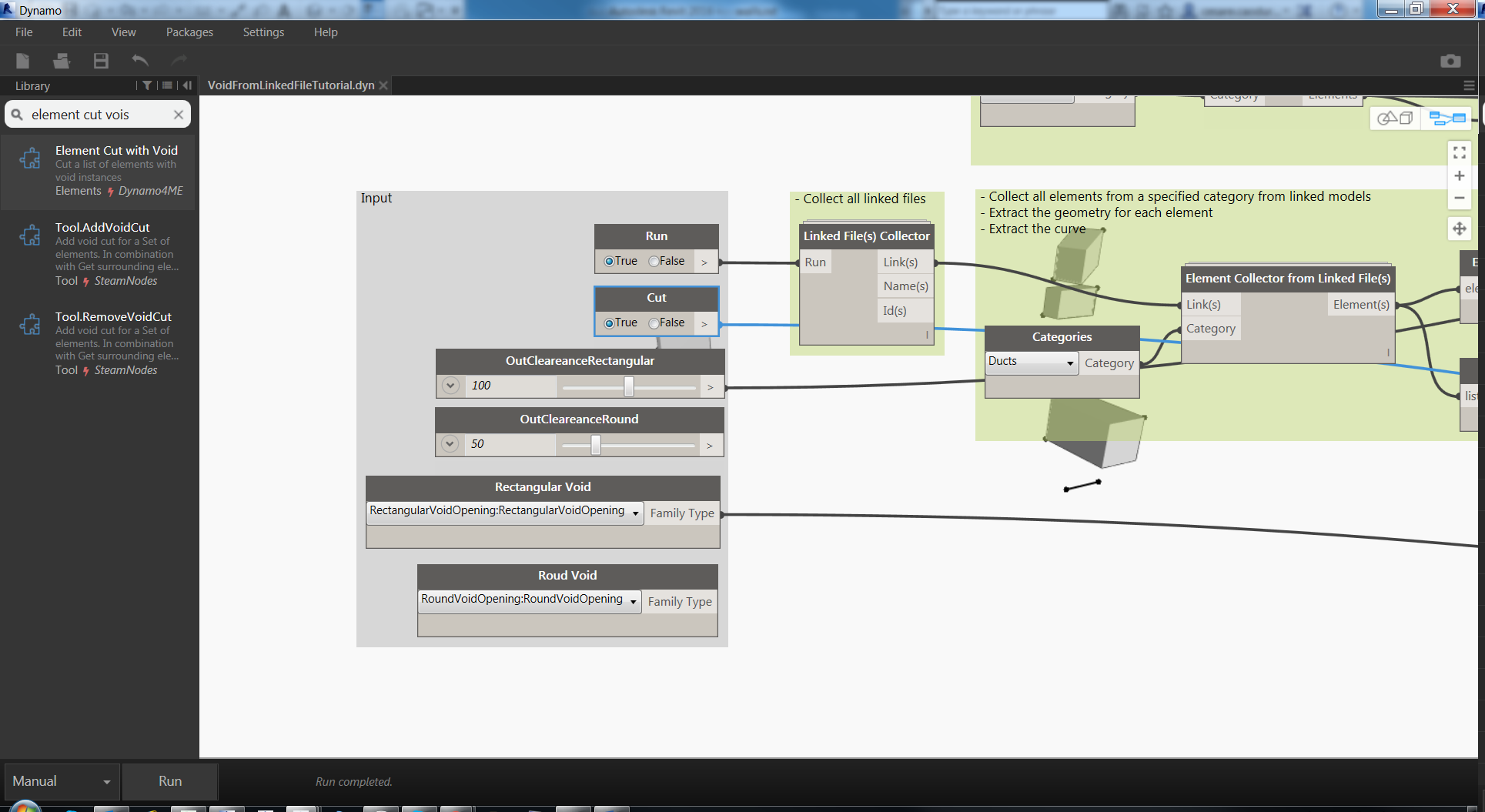
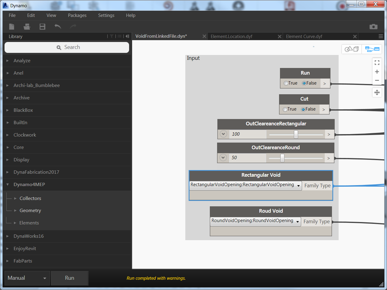
After the setup of the platform we can start with definition of input:
Boolean nodes for workflow execution
Run: execute the definition
Cut: perform the void cut
Two different clearances for both rectangular and round type voids: those will control the free space around the intersection
Two different Family Types node to choose the different void families
After the placement of nodes I’m always trying to rename the node with a more familiar name especially for input nodes is a good practice. Then I’m using a color code strategy to group nodes according to the workflow stage:
Grey > Input
Green > Main workflow operations
Magenta > Revit operations
Yellow > External Output (i.e. Excel data extraction)
Is also important to write a brief description in the title of the group to explain the operation performed inside. I’m getting old and after couple of days I forgot everything so, is better to write…Verba volant, scripta manent.
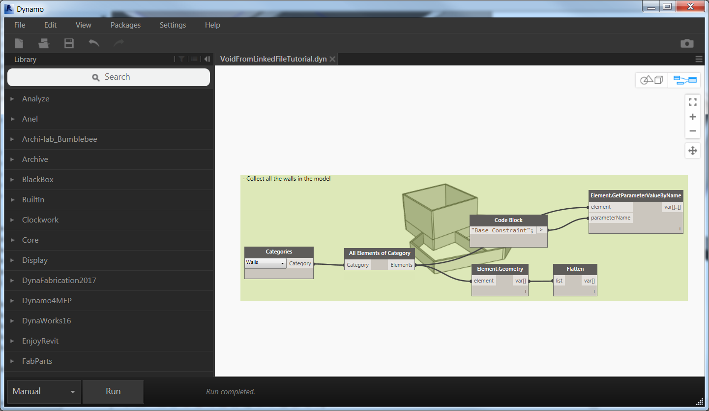
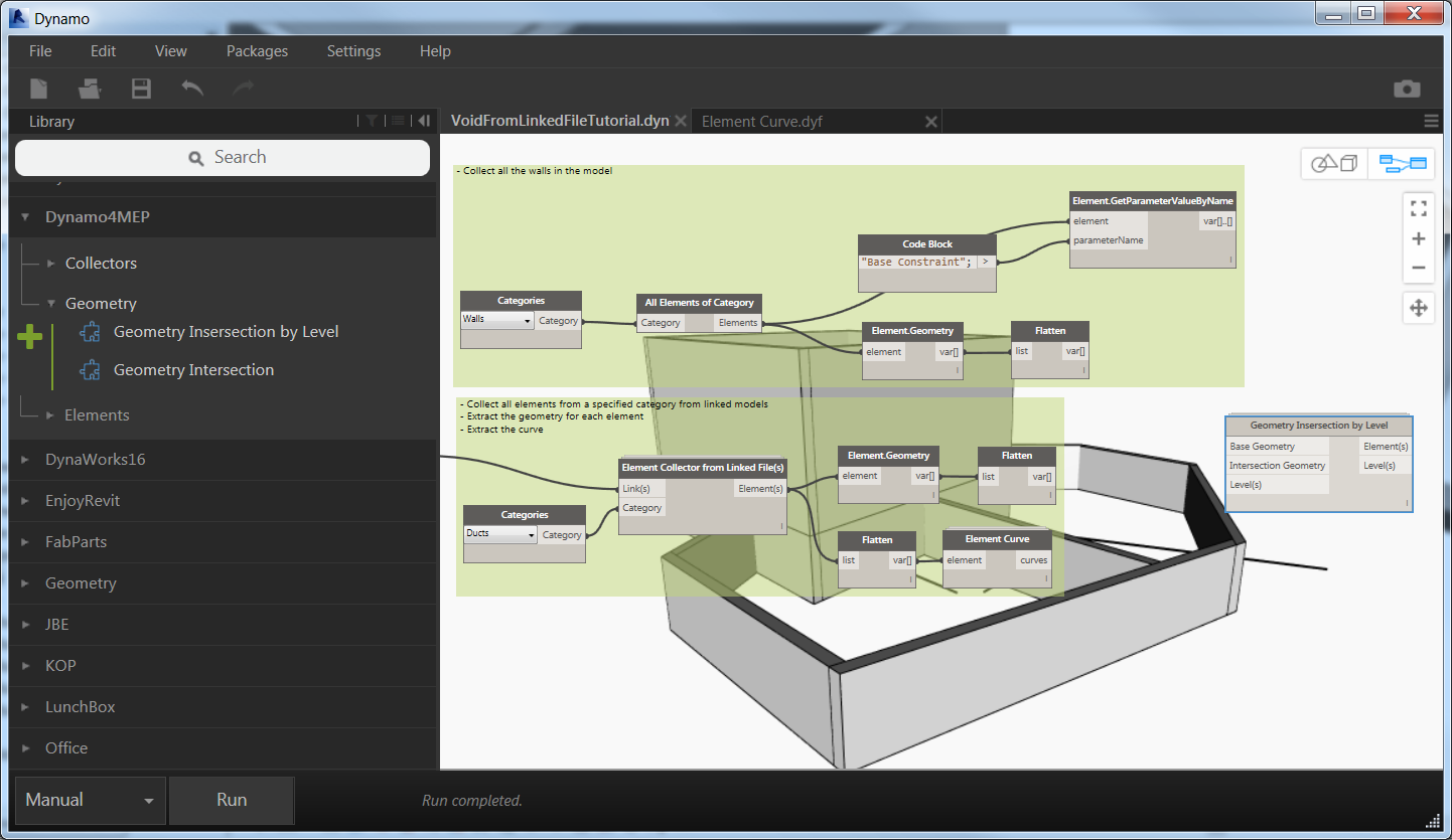
Now we can collect all the walls in the project and extract solid geometries and the base constraint level (this will be useful to link each void to a particular level and get the elevation as a relative offset)
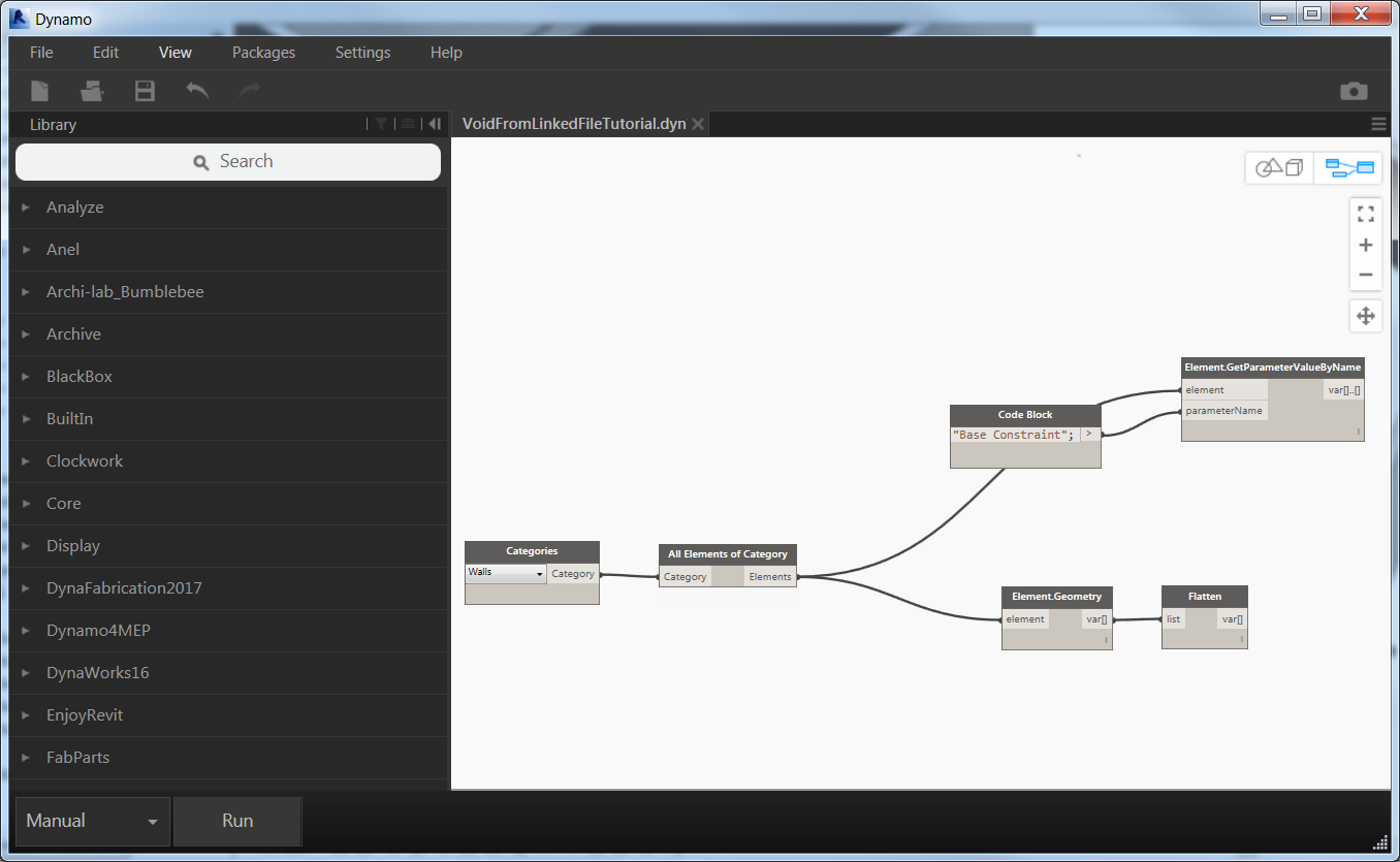
Categories + All elements of categories to collect all the walls in them model
Element.Geometry extract all the solid related to a 3D element and Flatten remove all the sub-list to create a simple list of elements
Element.GetPatameterValueByName doesn’t need any explanation just we need to feed the name of the parameter we want to be extracted and the list of elements.
 If you’re not able to see elements in the background try to zoom in the background view. First click on the button on the top right to switch to the background preview and then right click and Zoom to fit.
Then Switch again to graph view navigation.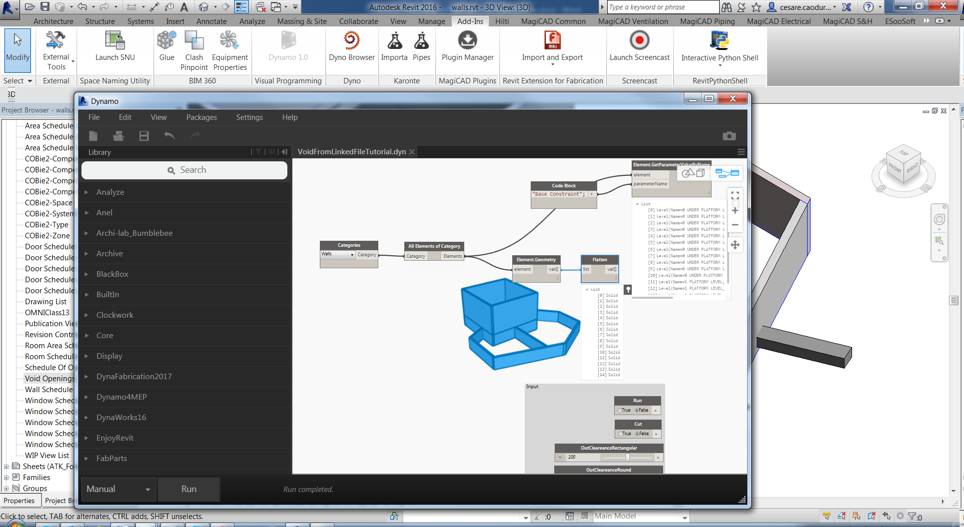
Now we can select all together the nodes and group them, don’t forget to write some comment on the title of the group.
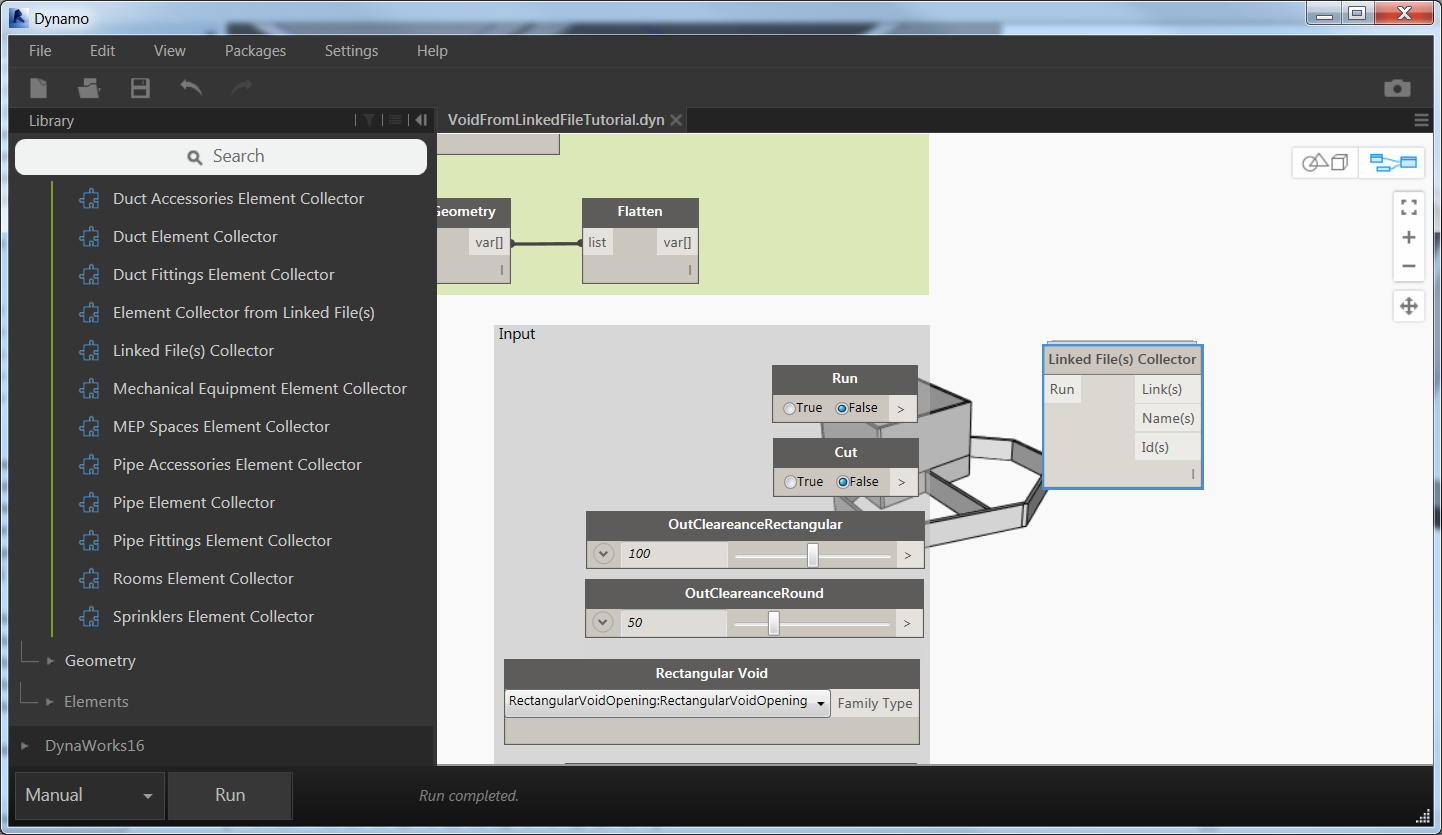
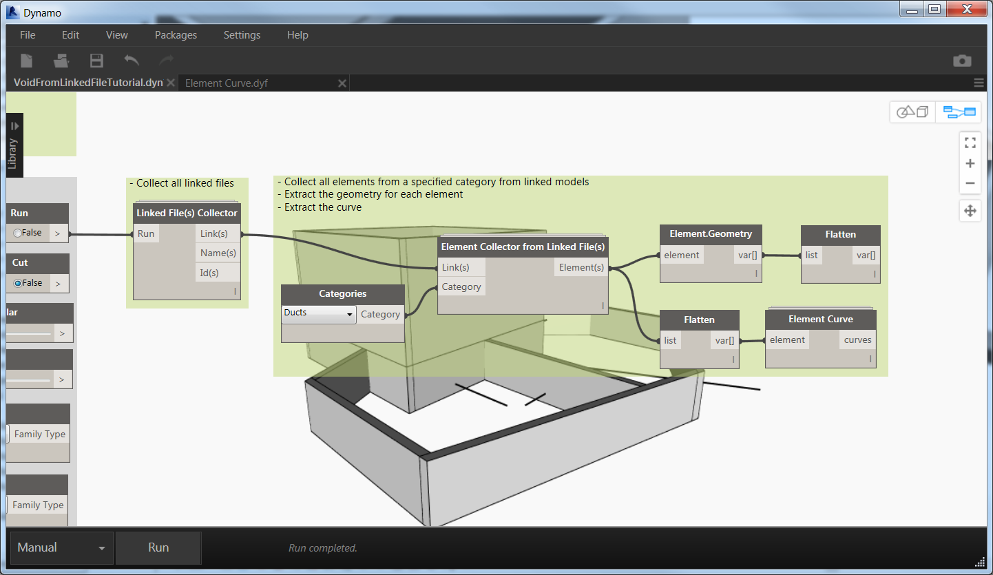
We reached the first important step of the workflow, we are ready to use the first custom node from the Dynamo4MEP package, this node is Linked File(s) Collector. The name is clear, the output of this node is the list of all the linked models available in this project.
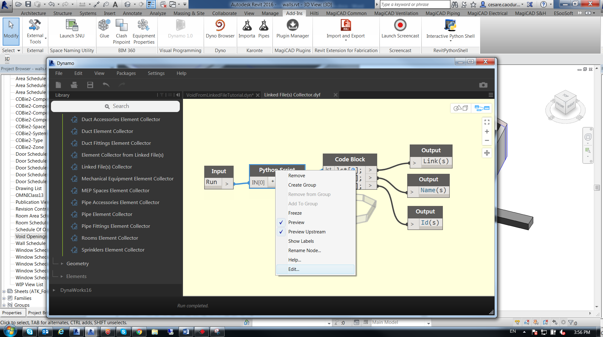
Let’s have a brief look into the code of the node, right click on the node and Edit Custom Node

Again right click on Python Script and Edit
Finally you can access the code inside the node that performs the action
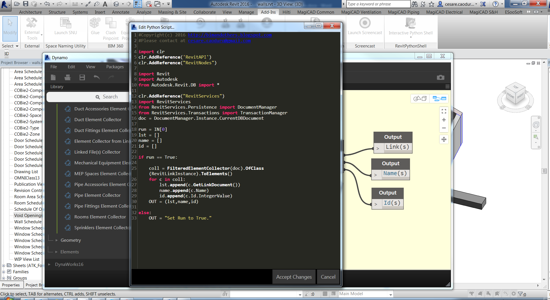
In the first part we have all the declarations and import statements, most of them are common for all the python scripts (I’ve a common starting point like a template to write nodes)
Second block all the inputs as array, it depends on the number of input that you’re providing the IN array will be longer
Third block is actually the core of the node where you’re taking actions. In this particular node I’m using a Boolean variable (the only input of the node) to start or stop the actions in the node. Then an API call, collect all the elements of a particular type (in this node I’m collecting all the elements of type link) and, with a loop, I’m just creating an array with the document pointer, the name and the ID of the link
The OUT variable is a system variable to define the output of the node
Close the python window to go back to definition of custom node and the last operation in the node is to define the output available for the customer. Is easy to give a custom name but be sure to extract In the correct way the output from the code as a list of array. The code block is the best way to perform this operation as you can see from the picture.
Explore and study the custom nodes made by others is the best way to learn programming, try to open a node, make small modifications and experiment!
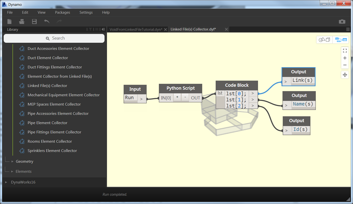
Ok stop dreaming too much we have lots of things to do, first of all to connect the collector node to the run node
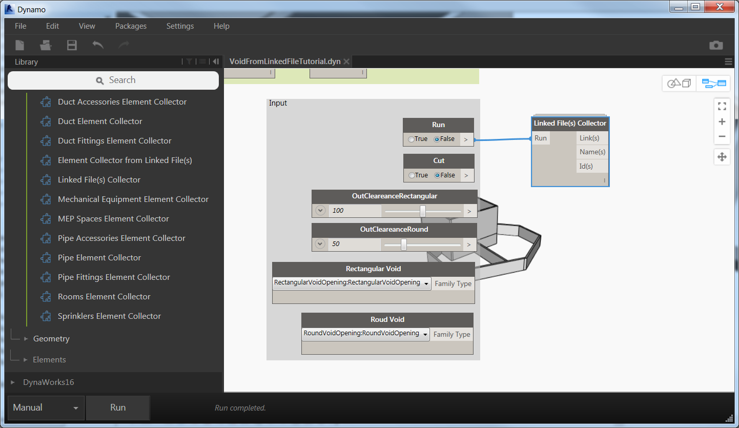
My suggestion is to work always in Manual mode to avoid unexpected crash (actually not too much unexpected). Then try to move the Run node to True and Run the definition.

Yes, all the 3 links are available now and ready to be explored by the next custom node Element Collector from Linked File(s). This node needs two input: the list of links and the category that you want to collect.
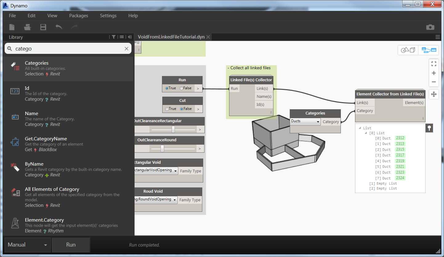
In this case all the ducts are in the same models but sometimes the can be in different links coming from different consultant, or simply split in different models because of the dimension and complexity of the project.
It seems strange but I’m commenting also single nodes sometimes, you never know who will use your definition and sharing is the most important lesson that you’ll learn from Dynamo.
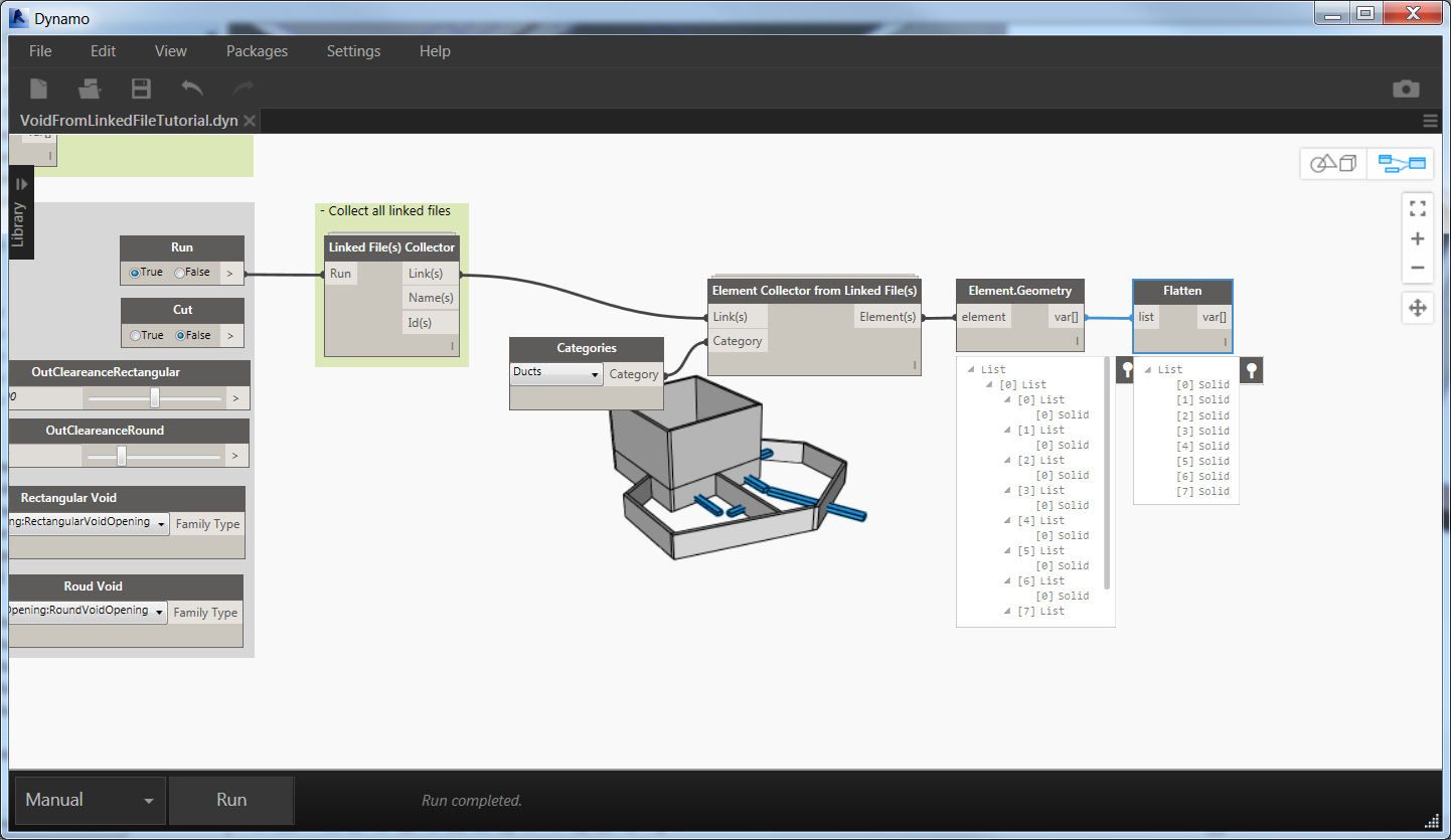
Element.Geometry and Flatten will extract all the solids and remove sub-lists…perfect!
What? Oh yes you want to have a look into the element collect node, but you know how to do it so what are you waiting for?!
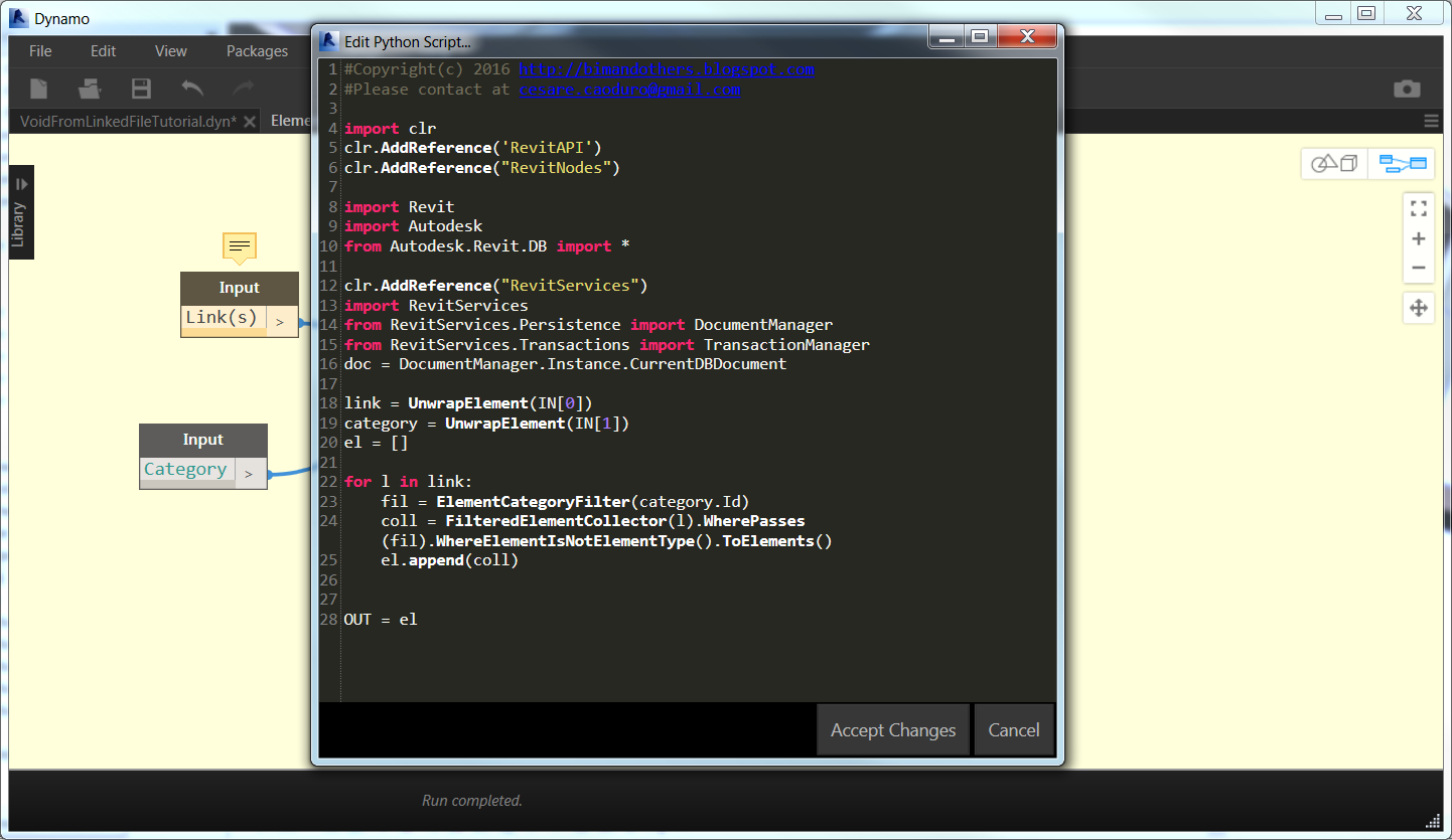
It is very similar to the previous one, the difference is the use of UnwrapElement function for inputs. Consult Dynamo Primer as starting point for your trip (http:\/\/dynamoprimer.com\/) with a focus on this chapter http:\/\/dynamoprimer.com\/09_Custom-Nodes\/9_Custom-Nodes.html.

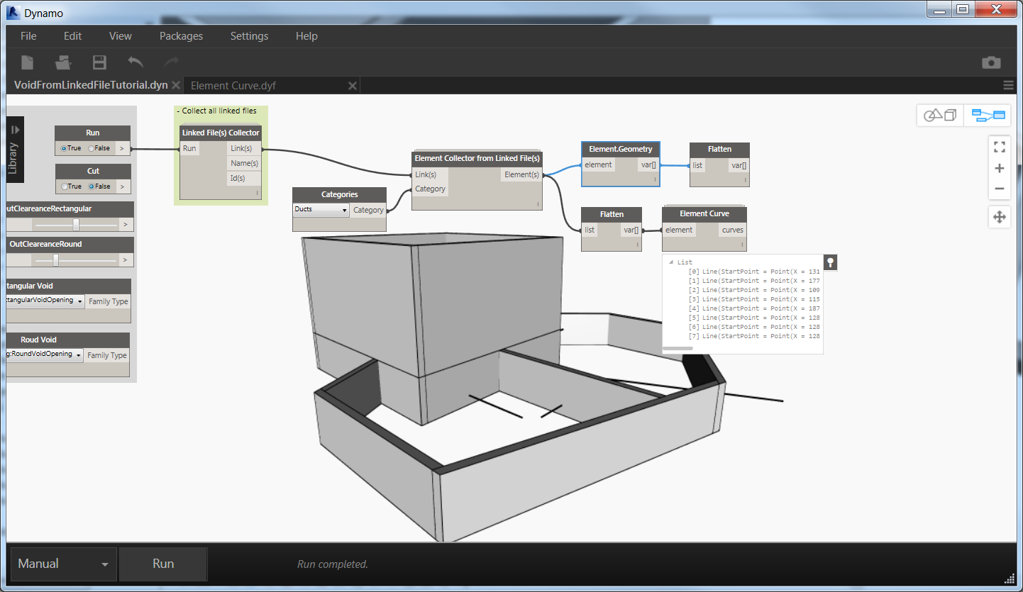
As last step for this part we use a flatten node to remove sub-lists and another custom node from my package Element Curve, to extract the center line of the duct, it’ll be useful later.
As much as the definition is getting complex we can hide some elements from the preview, simply with right click on the node and removing the flag, sometimes you’ve to remove from several nodes, like in this case we need to remove from both the Element.Geometry and from the Flatten node.
This group will be the base also for other categories like Pipes and Cable Trays, the procedure is exactly the same, you can choose to have separate dynamo file for each type of category or, like me, to have a single dynamo file checking for all categories at the same time.
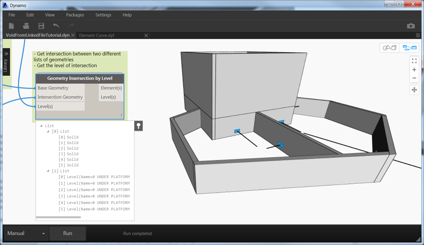
Yes now we have walls, we have ducts we need to check intersections between them…how? Of course with a custom node. Why we need a custom node? Because we need to perform an iteration for each wall in the project with each duct and find if there are interferences.
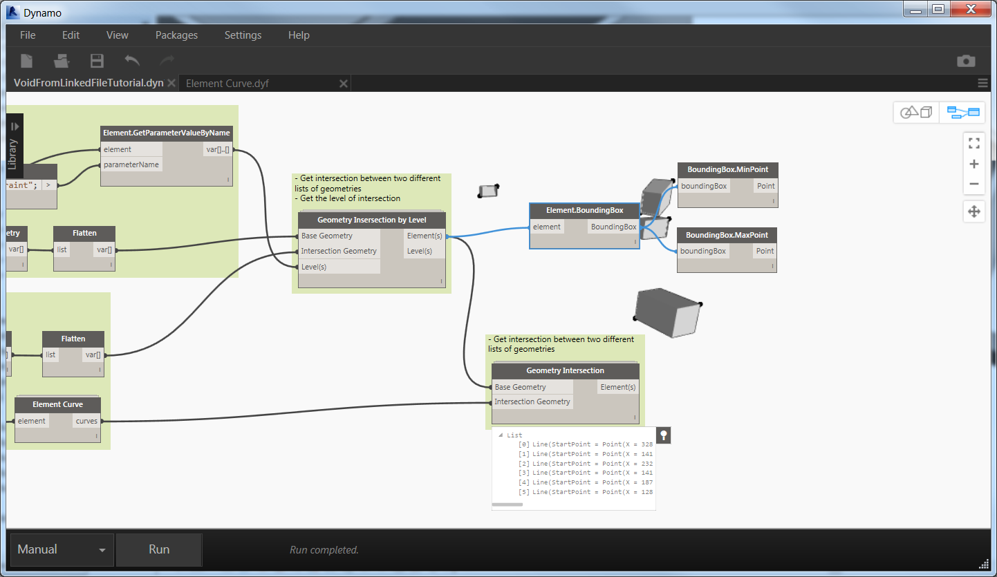
I choose to create two different nodes for this operation: one collects interference and level at the same time, the second one only intersection. Sometimes you don’t need the level information but only the intersection. We’ll use both of them.

Base Geometry: Walls - Intersection Geometry: Ducts - Levels: output of the level parameter extraction
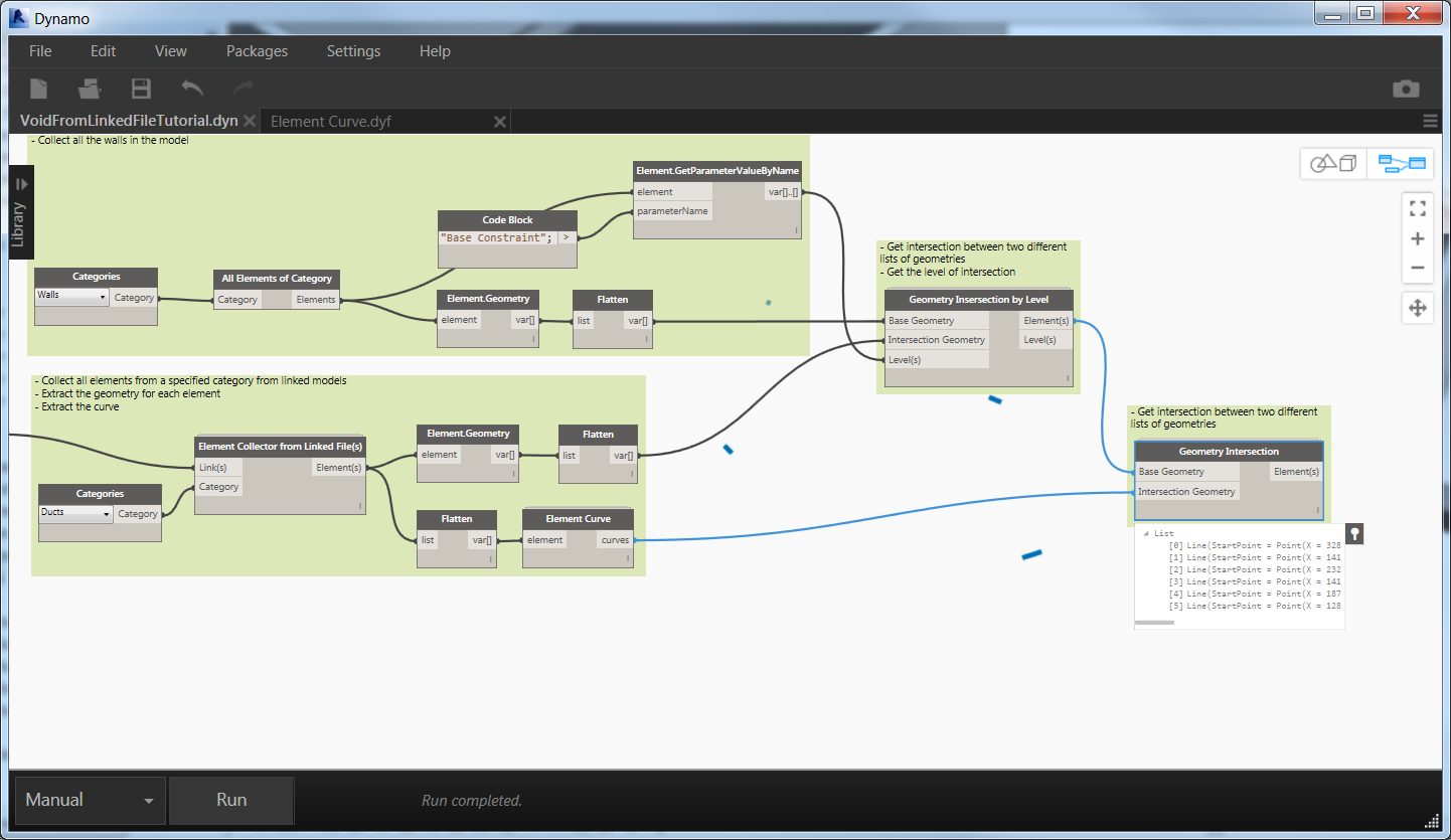
One of the critical issue for this kind of procedure is to understand the direction of the void. Is not simple to understand the normal vector or the direction of the duct and for this I’ll use a trick.
We’ll use the center line of the duct extracted before and intersect this line with the intersection solid coming from the previous part, the result will be a small line exactly pointing to the direction of the void that we have to create. At the same time, we can easily extract the center point of this small line which will be the insertion point of our void family.
Now we can use the other type of Geometry Intersection because we don’t need the level information: Base Geometry the intersection solid and Intersection Geometry the curve extracted from the duct.
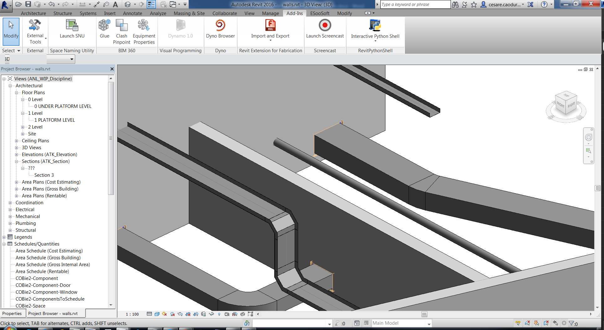
Hide a little bit of element to be able to see this small line.
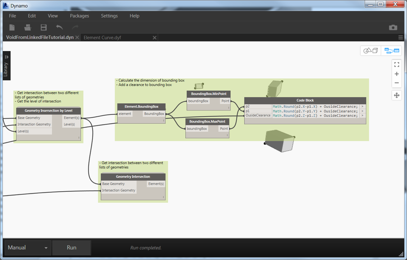
Yeah! Everything is going and now we are ready for a step forward. Now the worst part is coming: calculate the dimension of the void and, most difficult, calculate the direction using the line that we just extracted.
There’re many ways to calculate the dimension of the void: extract edges of the solid and calculate the length in each direction, extract all the vertex and find the difference between those, we’ll use the bounding box method.
With the bounding box we can achieve a better result in a smart way. When we encounter a wall with a sloped system the best way to create the reservation is to create a cuboid opening covering the entire volume of the intersection instead of creating a sloped opening, try to ask to construction team to cut a diagonal opening in a concrete wall! Different is if the pipe, for example, is casted directly in the concrete but, in this case, you don’t need to create a reservation.
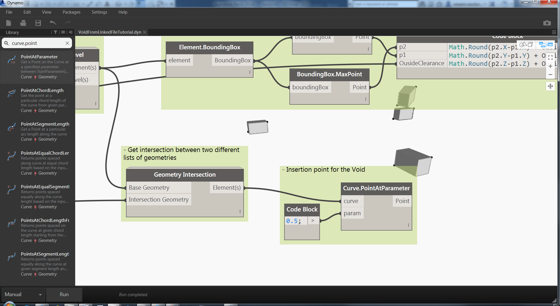
So the basic idea is to calculate the dimensions based on the max and min point of the bounding box and a code block. Yes, I love code block because you can combine multiple operations together instead of using different nodes.
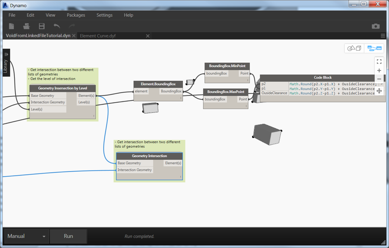
Math.Round(p2.X-p1.X) + OusideClearance;
Math.Round(p2.Y-p1.Y) + OusideClearance;
Math.Round(p2.Z-p1.Z) + OusideClearance;
p2 is Bounding Box Max Point
p1 is Bounding Box Max Point
Math.Round is the function to round floating number to the closest integer
OusideClearance is one the input coming from the e beginning of the definition
Now we have the dimensions for the void according to the bounding box of the intersection. We’ll use those dimension later with the custom family.
Next step is to find the insertion point for the void but this is very easy. We have the intersection line between the center axis of the routing and the intersection geometry. So we need only to calculate the center point of this line and sore this point.
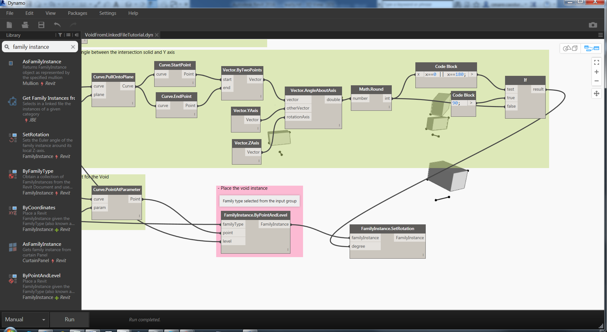
Before placing the void in the project I would like to concentrate on how to calculate the correct rotation of the void to be perpendicular to the surface al parallel to the routing.
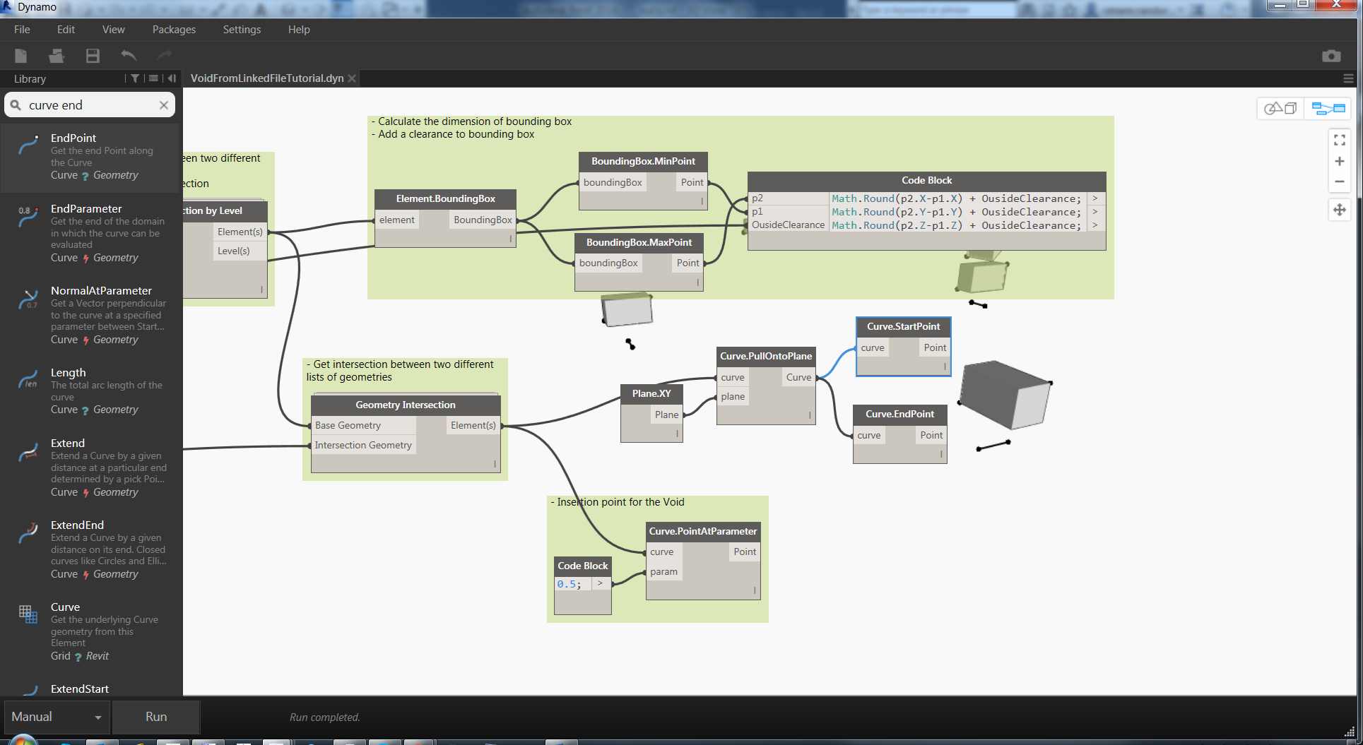
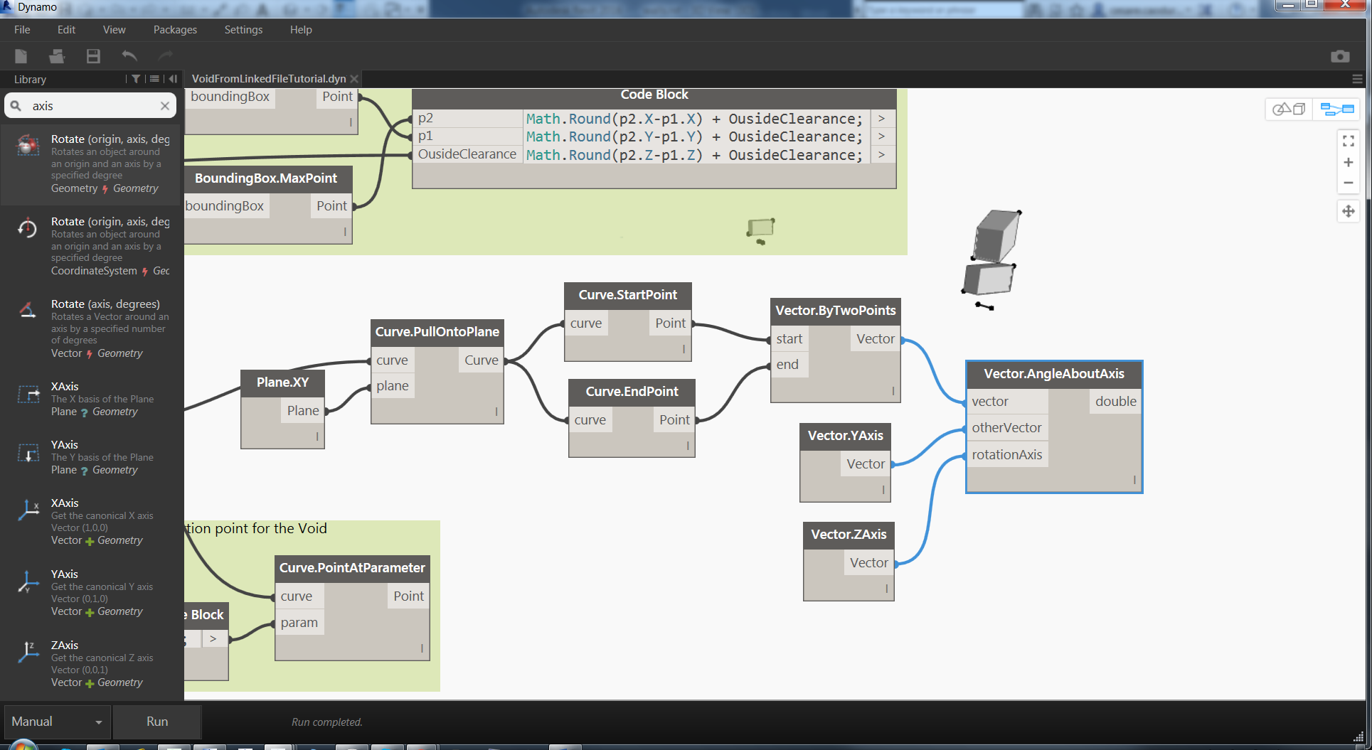
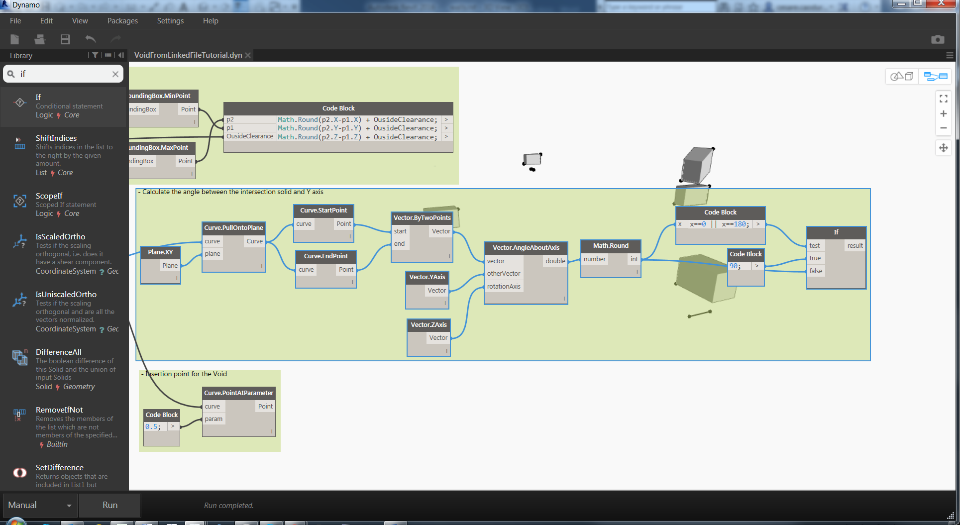
Again the curve will be useful for this purpose because is parallel to the routing. We have to calculate the angle between this line and the Y axis and then apply this rotation to the family. I’ll use the vector aligned to the curve to be able to calculate angle between two vectors. The first part is not essential, to visualize the curve I’m projecting this curve on the XY plane.
To simplify the validation of the angle we can round the result with the node Math.Round. The last check is about the angles 0 and 180. If the value of the angle is equal to those values we have to rotate 90 degrees the family otherwise we can take the value from the node.
Ok now it’s time to create the void, place it and provide the correct dimensions.


All the void are place in the correct position but still not rotated. We can now apply the correct rotation using the node FamilyInstance.SetRotation. The rotation is coming from the previous block.
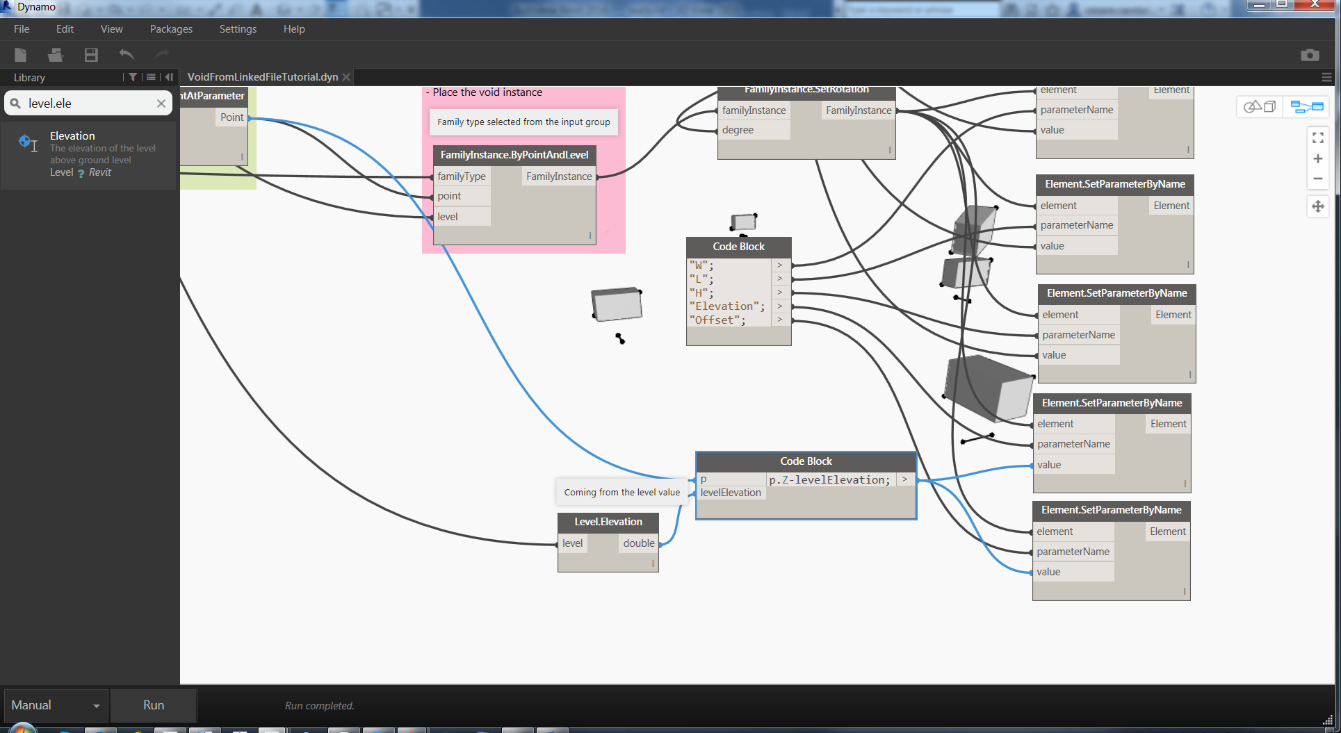
Finally set dimensions

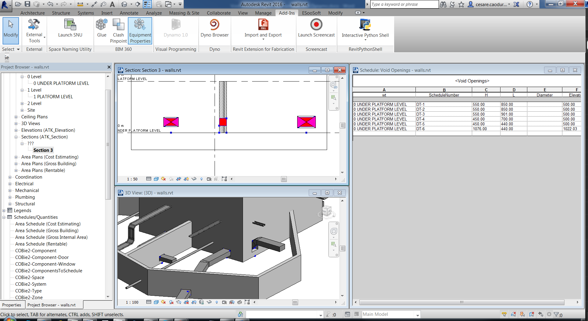
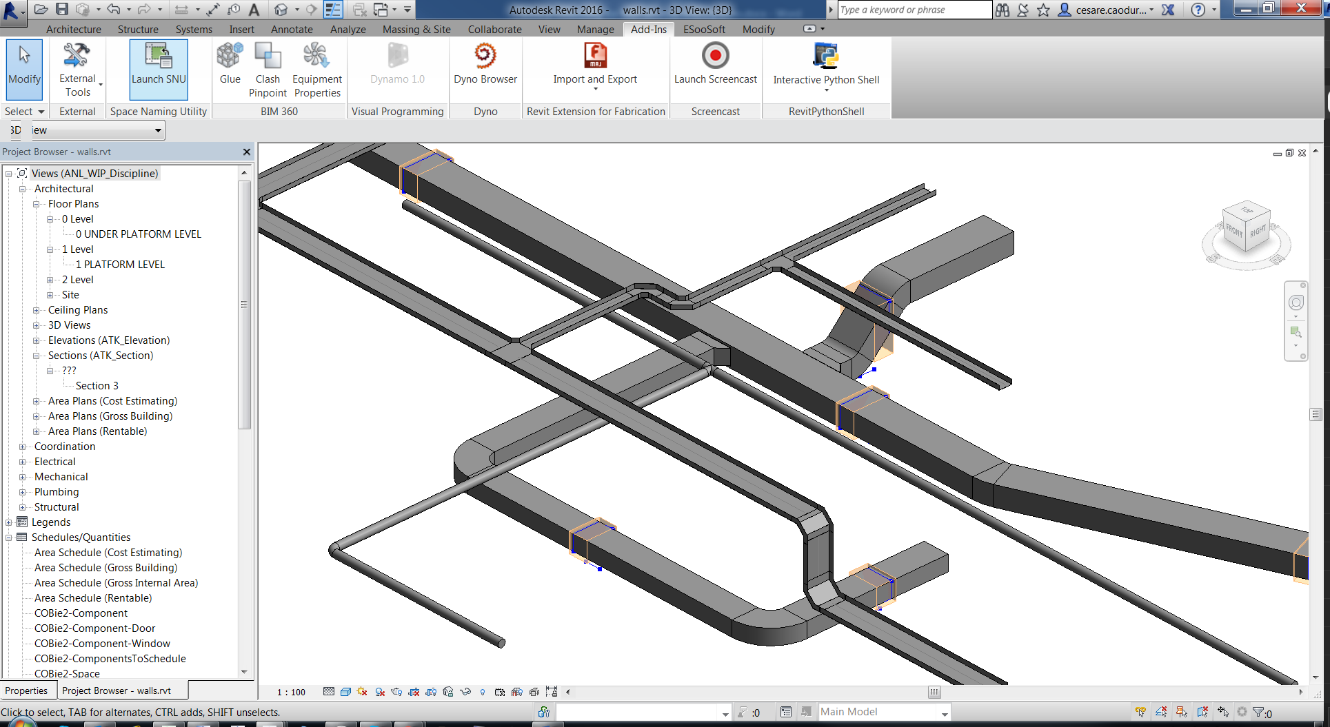
Run the script and, if all the connection are correct, you will see the correct orientation and dimension for each void. Cool!
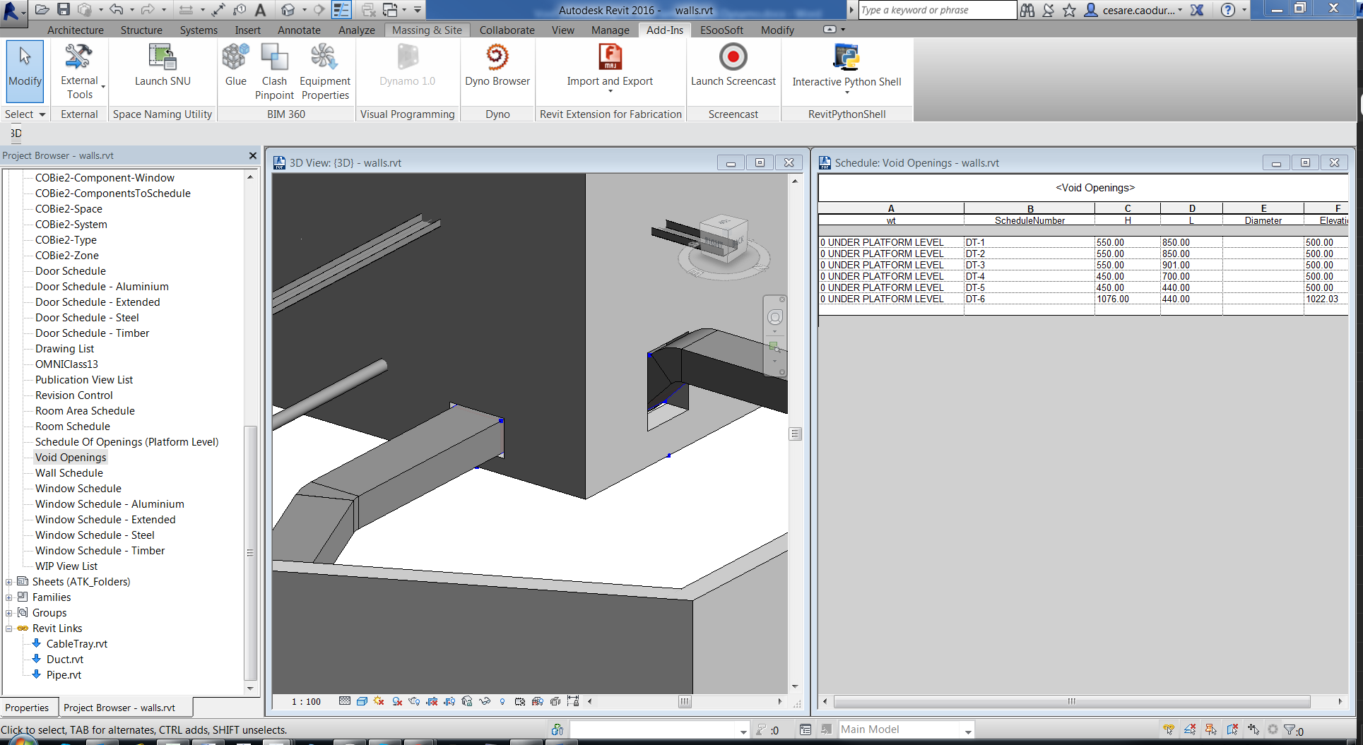
Just a few more parameters are required for each element: first of all, the value of the offset. This is coming from the difference between the Z value of the insertion point and the level elevation. Is an offset not an absolute elevation so we need to remove the level elevation. The same value will be stored in another parameter to be used in schedule (as you know we can’t use offset value in the schedule!).
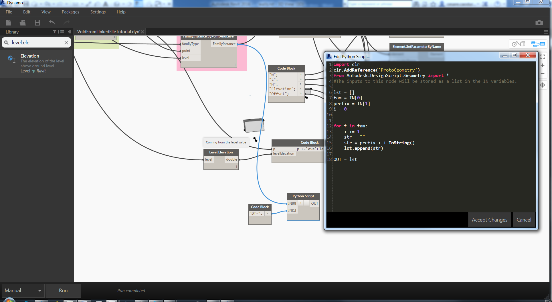
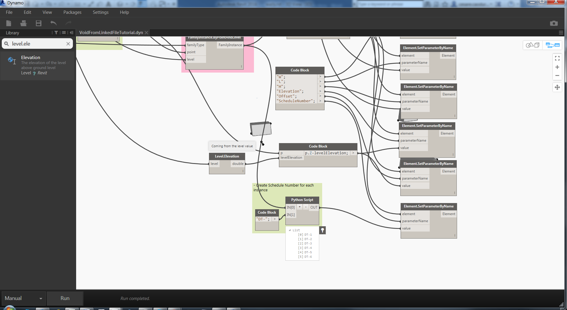
Last but not least I thought about a parameter as code. I called this parameter ScheduleNumber aand is basically a progressive number with a prefix. There’re many ways to achieve the same result but I like to write a python code, just because is cool.
This node accepts family instances to be able to iterate on each of them and a prefix as a string.
And the result is a list of strings.
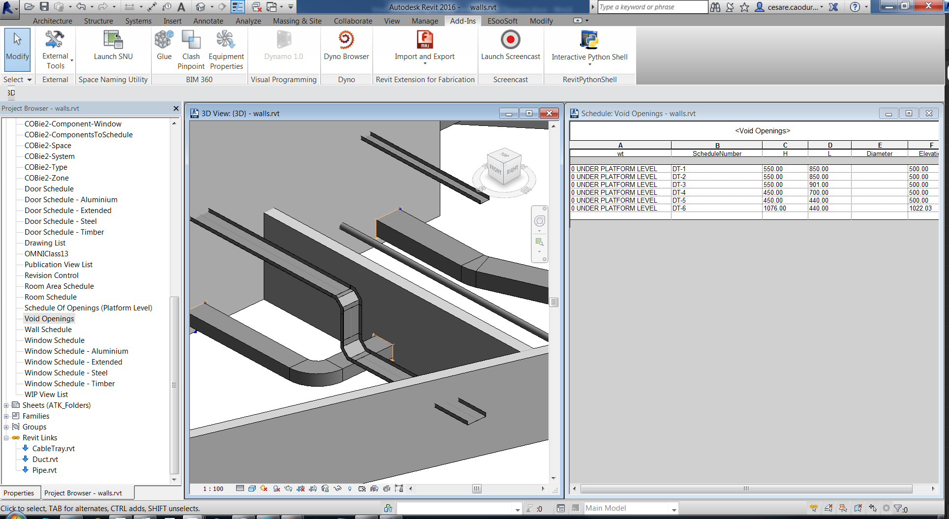
Yes we have finished!
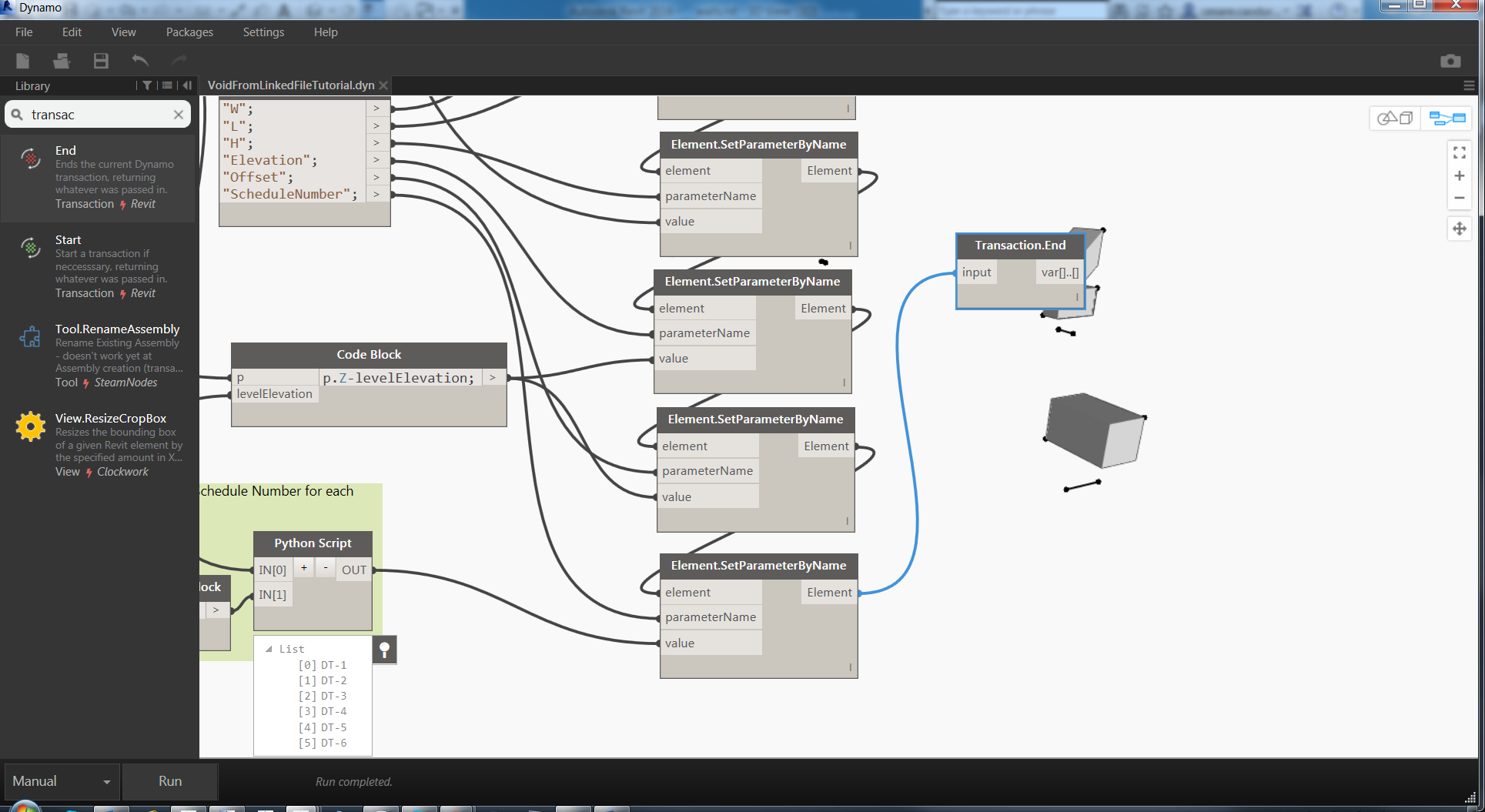
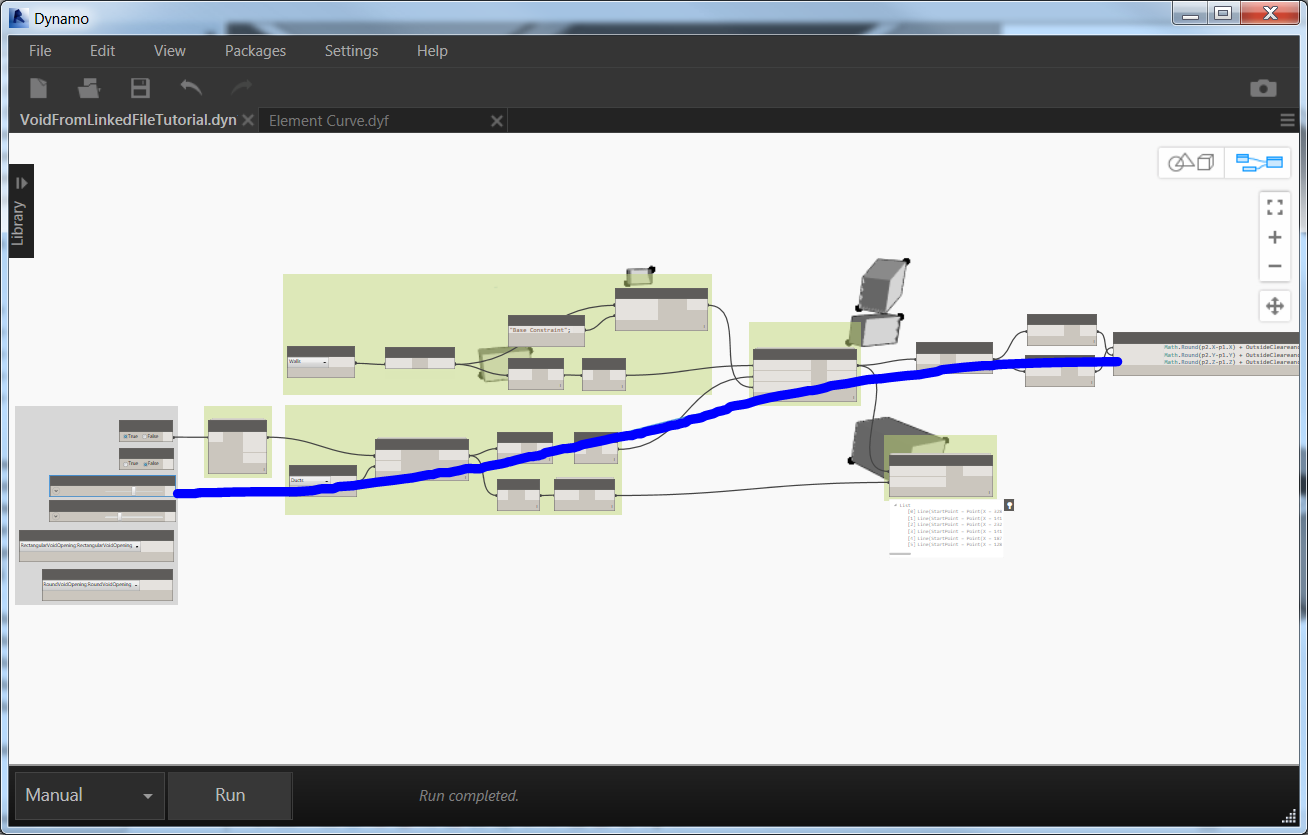
It’s difficult to understand the flow of elaboration in Dynamo so, when you’ve more than one set parameter node, to feed the output of one node to the input of another node, like in image before. It seems like a snake but, in this way the result is more predictable (I said more, not predictable).
After these nodes to execute definitely the operations, I always use a node Transaction.End
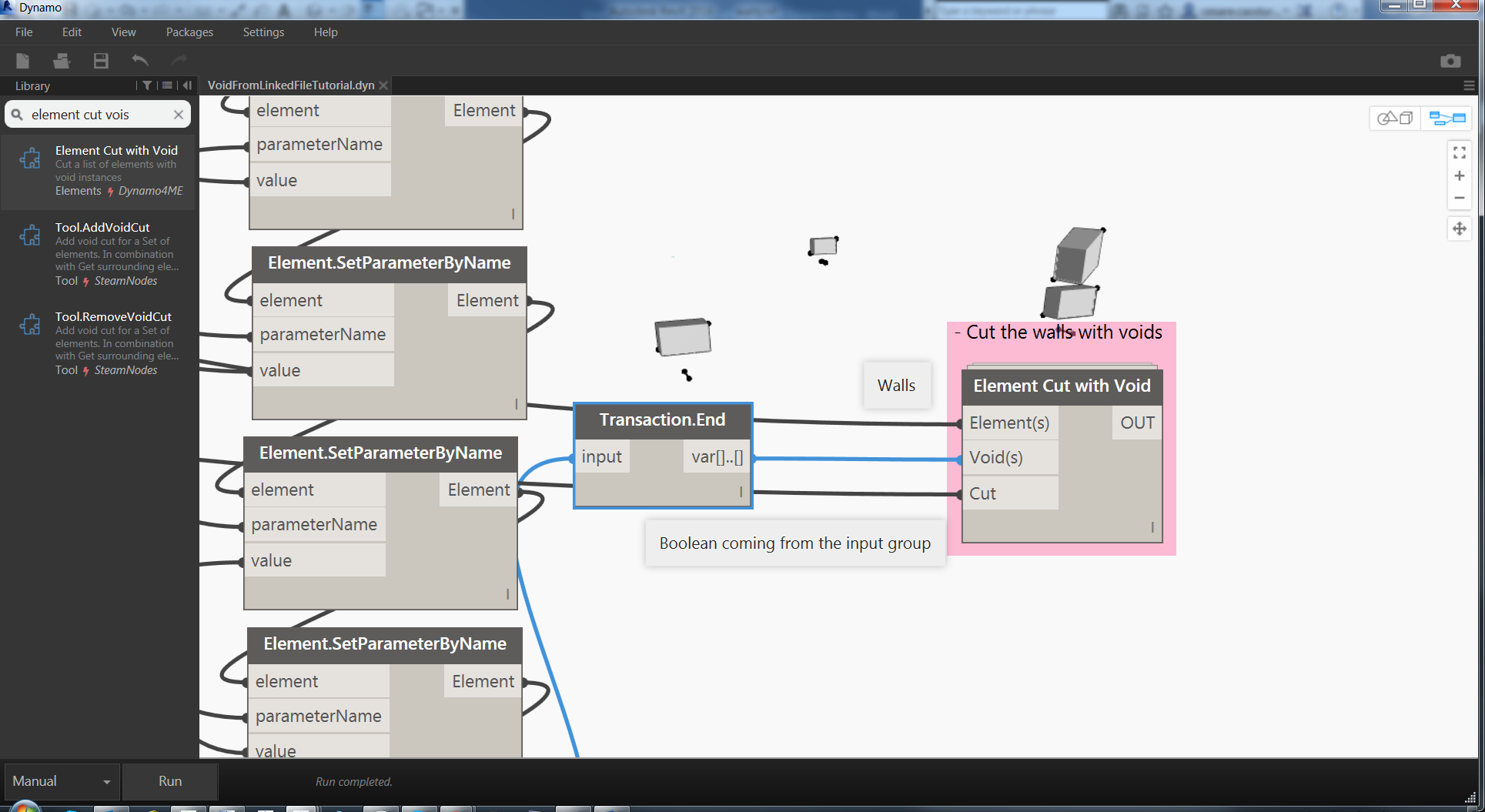
You can use my node Element Cut with Void. In the first input the elements coming from the list of walls, the second input are the void family instances and the third is the Boolean input coming from the input group.
Just change Cut on True and run the script.